Rotating electric machine control system and vehicle drive system including the rotating electric machine control system

A technology for rotating electrical machines and control systems, applied in control systems, motor control, motor generator control, etc., can solve problems such as the voltage increase of the frequency conversion part, and achieve the effect of suppressing heat generation

CN101682290AActive Publication Date: 2010-03-24AISIN AW CO LTD
2 Cites 4 Cited by

Patent Information

Authority / Receiving Office
CN · China
Patent Type
Applications(China)
Current Assignee / Owner
Publication Date
2010-03-24

Smart Images

  • Figure 1
    Figure 1
  • Figure 2
    Figure 2
  • Figure 3
    Figure 3
Patent Text Reader

Abstract

A rotating electric machine control system comprises a direct-current power supply, a rotating electric machine, an inverter for controlling current flowing through the rotating electric machine and acontrol device for determining the required number of revolutions that is the number of revolutions required for the rotating electric machine and a required torque that is a torque required, whereinthe inverter operates according to the required number of revolutions and the required torque. The rotating electric machine control system further comprises a torque limiting means for limiting thetorque of the rotating electric machine. The torque limiting means changes the mode of torque limiting control, depending on an inverter voltage (Vc) applied to a frequency conversion unit included inthe inverter.
Need to check novelty before this filing date? Find Prior Art

Description

technical field

[0001] The present invention relates to a rotating electrical machine control system and a vehicle drive system provided with the rotating electrical machine control system, wherein the rotating electrical machine control system includes a DC power supply, a rotating electrical machine, a power supply interposed between the DC power supply and the rotating electrical machine and convectively flowing through the rotating electrical machine. The current-controlled inverter is further provided with a control device for determining a requested rotation speed as a rotation speed requested by the rotating electrical machine and a requested torque as a requested torque, and the inverter is based on the requested rotation speed and the requested rotation speed determined by the control device. torque work. Background technique

[0002] As an example of such a rotating electrical machine control system, the applicant proposed in Patent Document 1 a method of limiting ...

Examples

Embodiment Construction

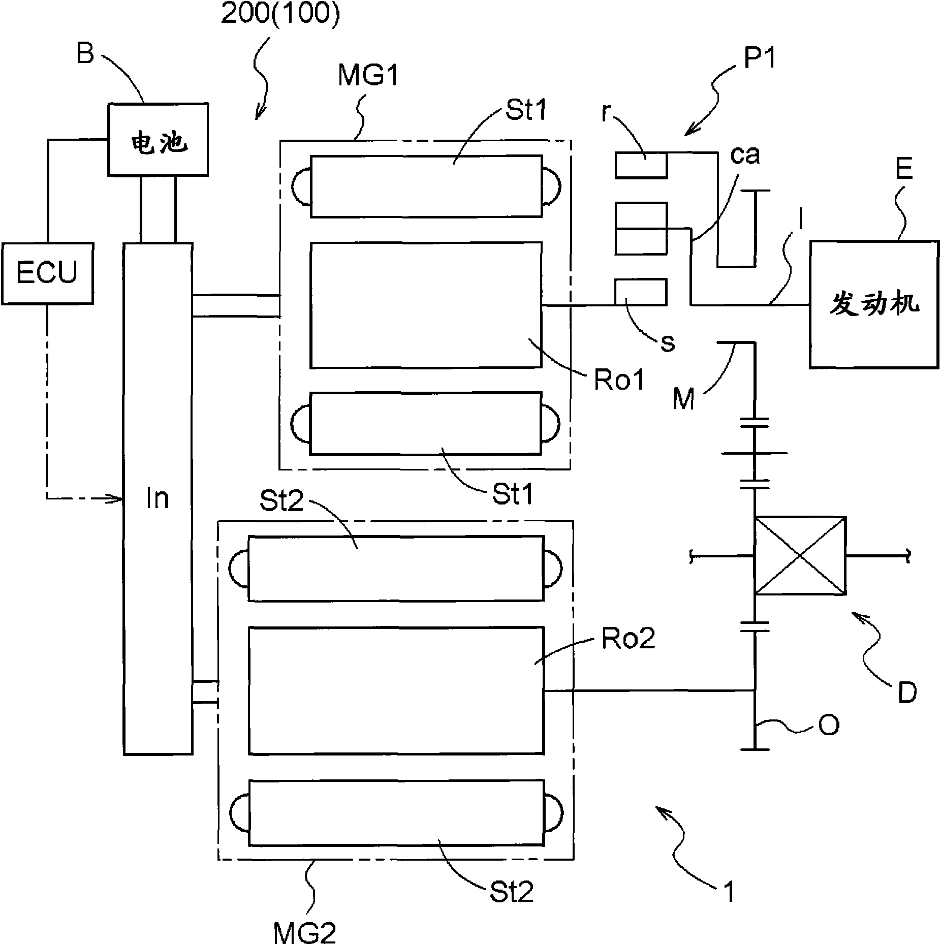
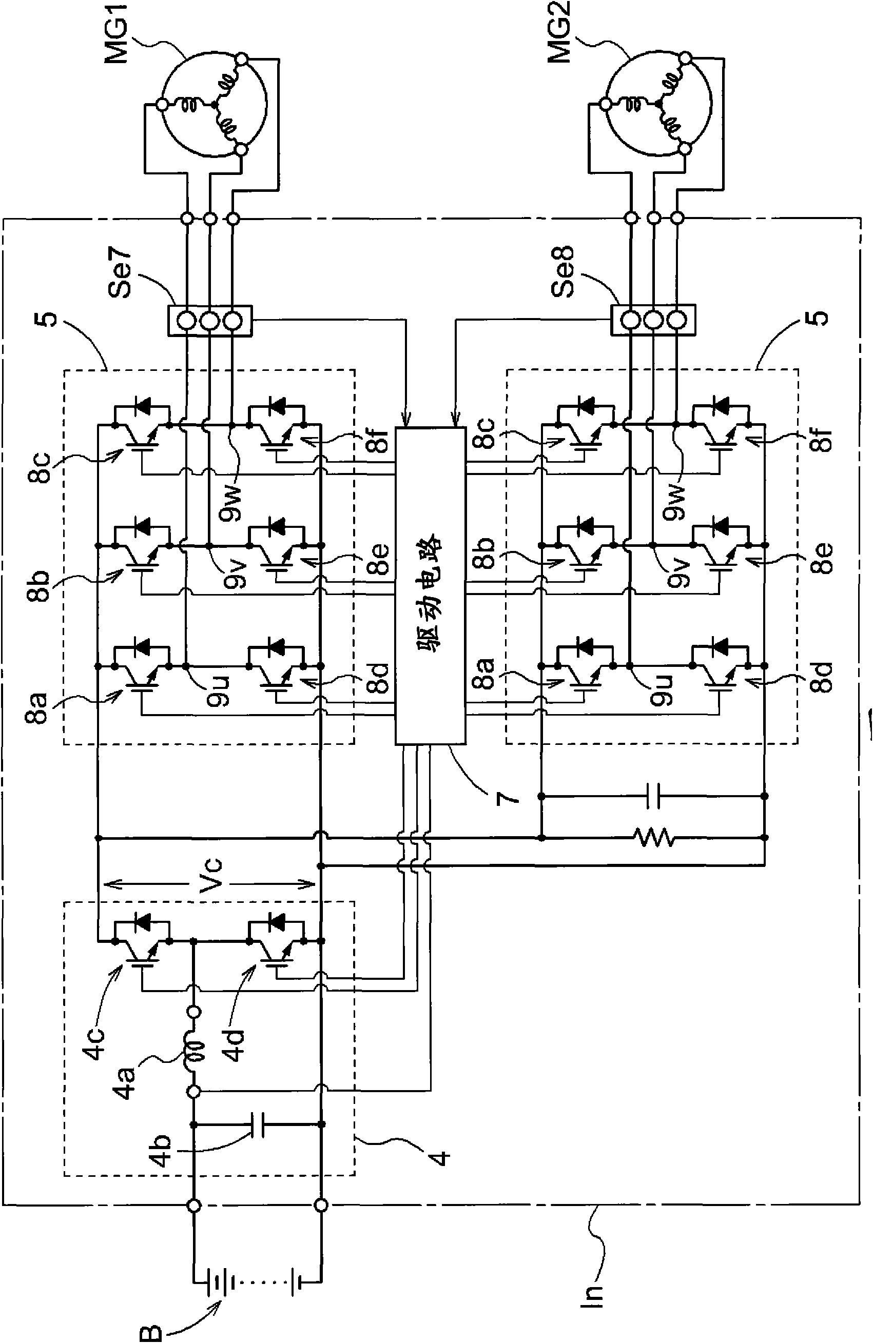
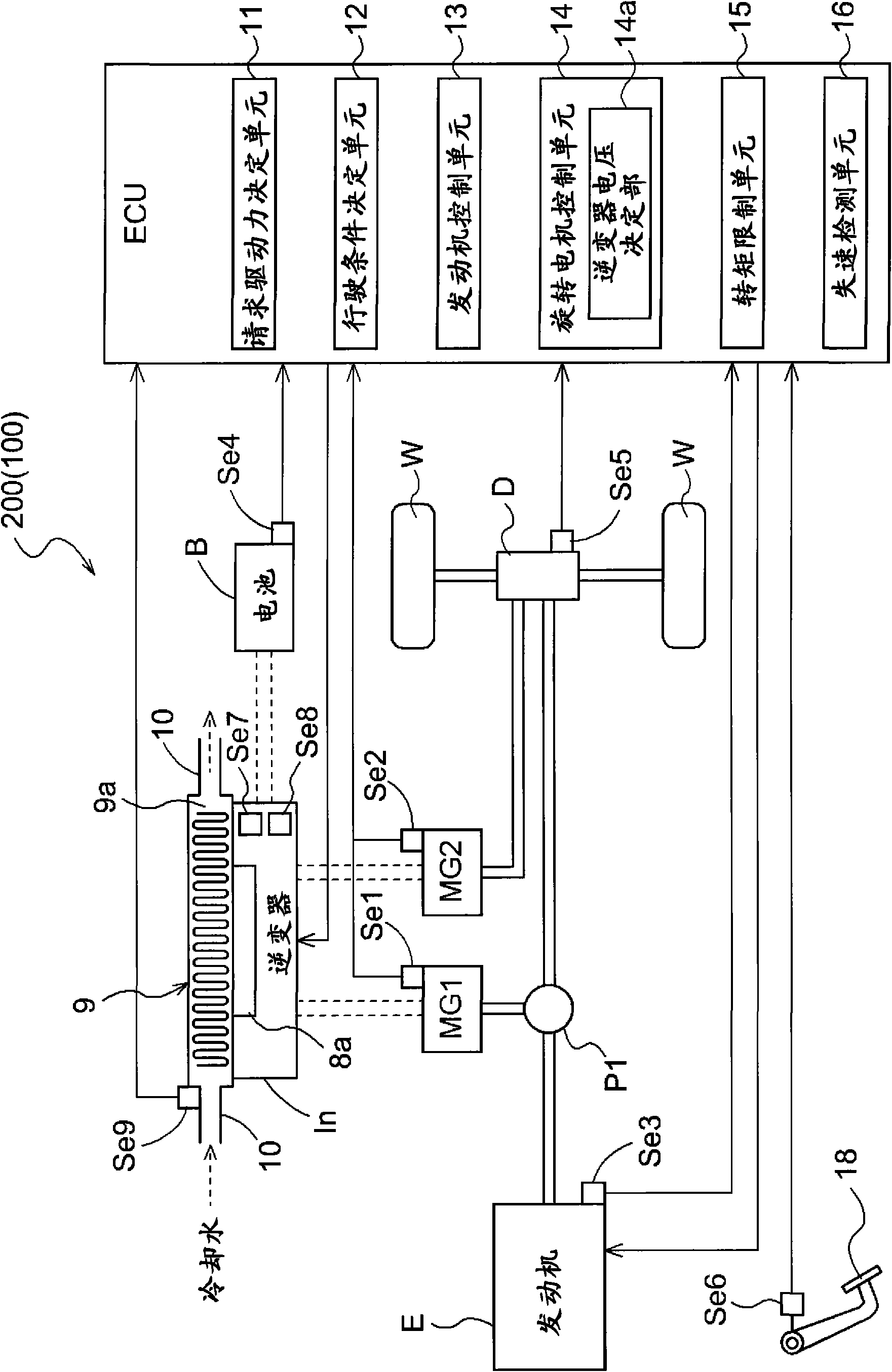
[0073] Hereinafter, an embodiment of the rotating electrical machine control system 100 according to the present invention will be described with reference to the drawings. The rotating electrical machine control system 100 is assembled in image 3 , represents the overall vehicle drive system 200 , which is used to control the operation of the rotary electric machines MG1 and MG2 included in the vehicle drive system 200 .

[0074] figure 1 is a schematic diagram showing the drive system of the vehicle drive system 200, figure 2 It is a schematic diagram showing a rotary electric machine control system mainly including an inverter In provided for controlling the rotary electric machines MG1 and MG2. image 3 It is a schematic diagram showing the whole of the vehicle drive system 200 including the control device ECU unique to the present application. image 3 The arrows in the middle solid line represent the transmission routes of various information, the double solid lines...