
Wire protection method and wire protection device

Active Publication Date: 2010-10-07
AUTONETWORKS TECH LTD +2
View PDF1 Cites 40 Cited by
  • Summary
  • Abstract
  • Description
  • Claims
  • Application Information

AI Technical Summary

Benefits of technology

[0007]In this configuration, the applied-current is detected every predetermine time, a present wire temperature is estimated using the applied-current, and the present wire temperature and the upper limit temperature that the wire allows for are compared. This makes it possible to, even in a case where the wire rise temperatures due to a short-circuited current that repeats turning on / off as illustrated in FIG. 11, reliably detect the temperature rise, break the applied-current before the wire reaches the smoking temperature, thereby preventing the wire from smoking. Besides, while a conventional thermal fuse is deteriorated due to inrush current, such a factor of deterioration is not included in the present configuration. Moreover, the present configuration provides accurate temperature estimation. Thus, the current can be flown and be used until just before the wire smokes.
[0008]Furthermore, because the wire temperature is estimated only by detecting the applied-current, the structure of wire protection can be easily configured.

Problems solved by technology

By the way, the method that attaches a temperature measuring element (such as a linear thermistor) to the wire harness itself and directly measures the temperature of the harness as disclosed in the above-mentioned publication causes inconveniences of complexity of the structure and increase of the cost.
Moreover, in a case where the temperature rises in a single wire located in a vicinity of the center, accurate tracking of the temperature is impossible.
Besides, while a conventional thermal fuse is deteriorated due to inrush current, such a factor of deterioration is not included in the present configuration.

Method used


Image

  • Wire protection method and wire protection device
  • Wire protection method and wire protection device
  • Wire protection method and wire protection device

Examples


Embodiment Construction

[0029]

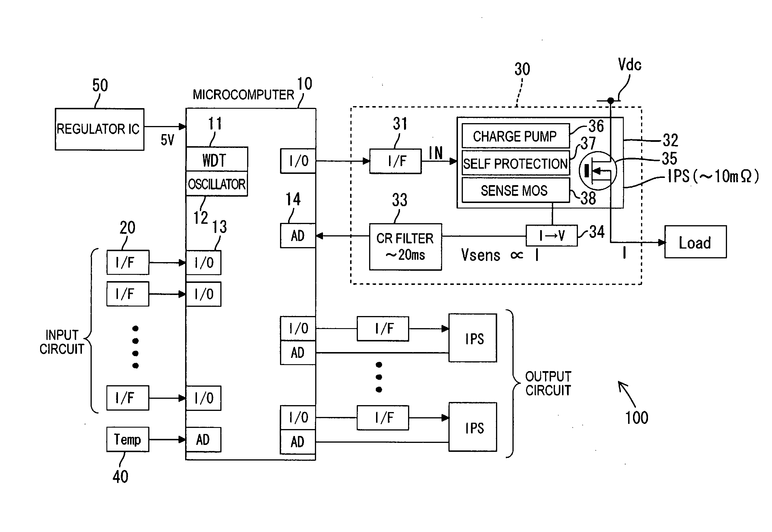
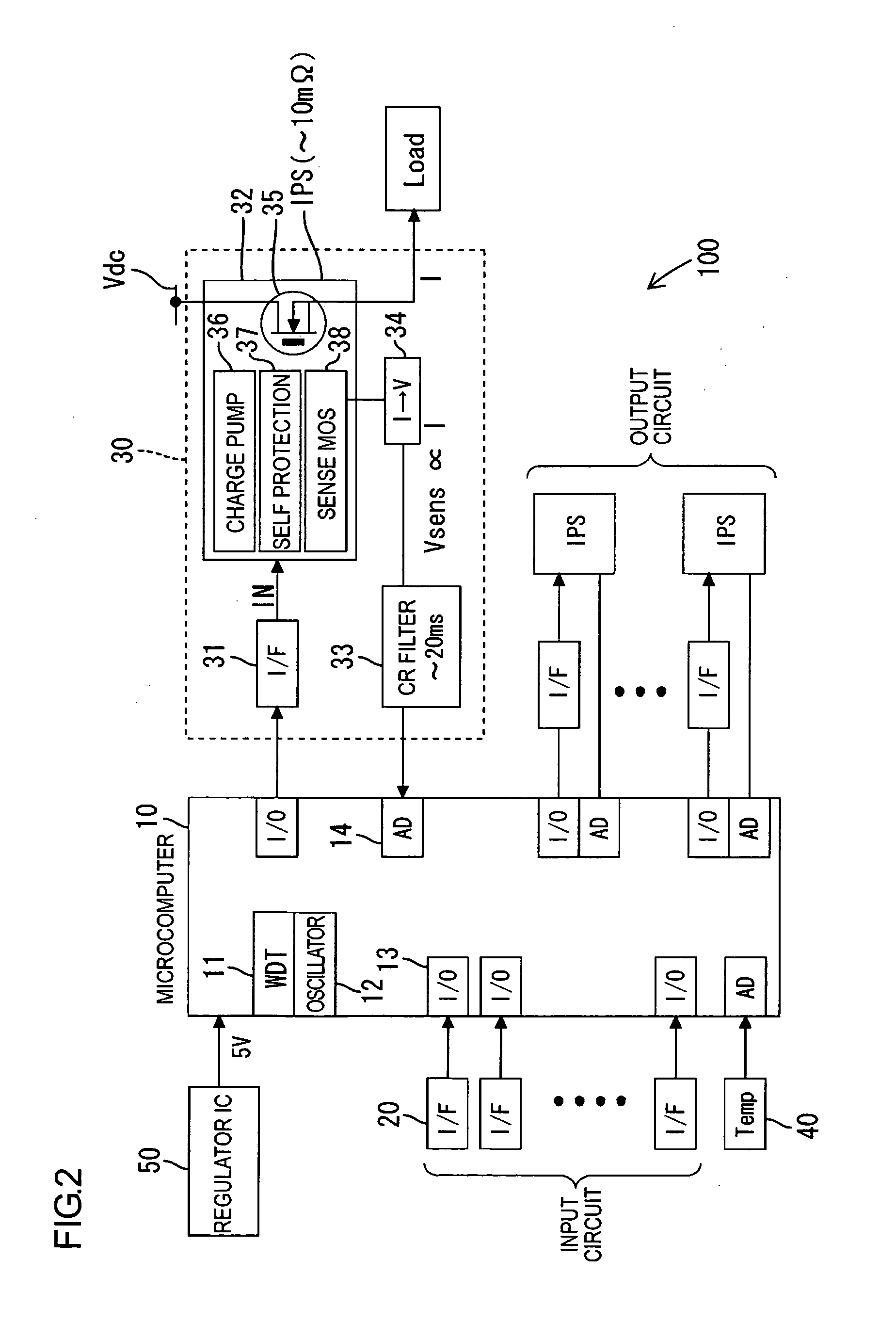
[0030]An illustrative aspect in accordance with the present invention will be explained with reference to FIGS. 1 through 5. While a vehicle wire harness is intended as a wire to be protected in this illustrative aspect, the wire to be protected is not limited to this.

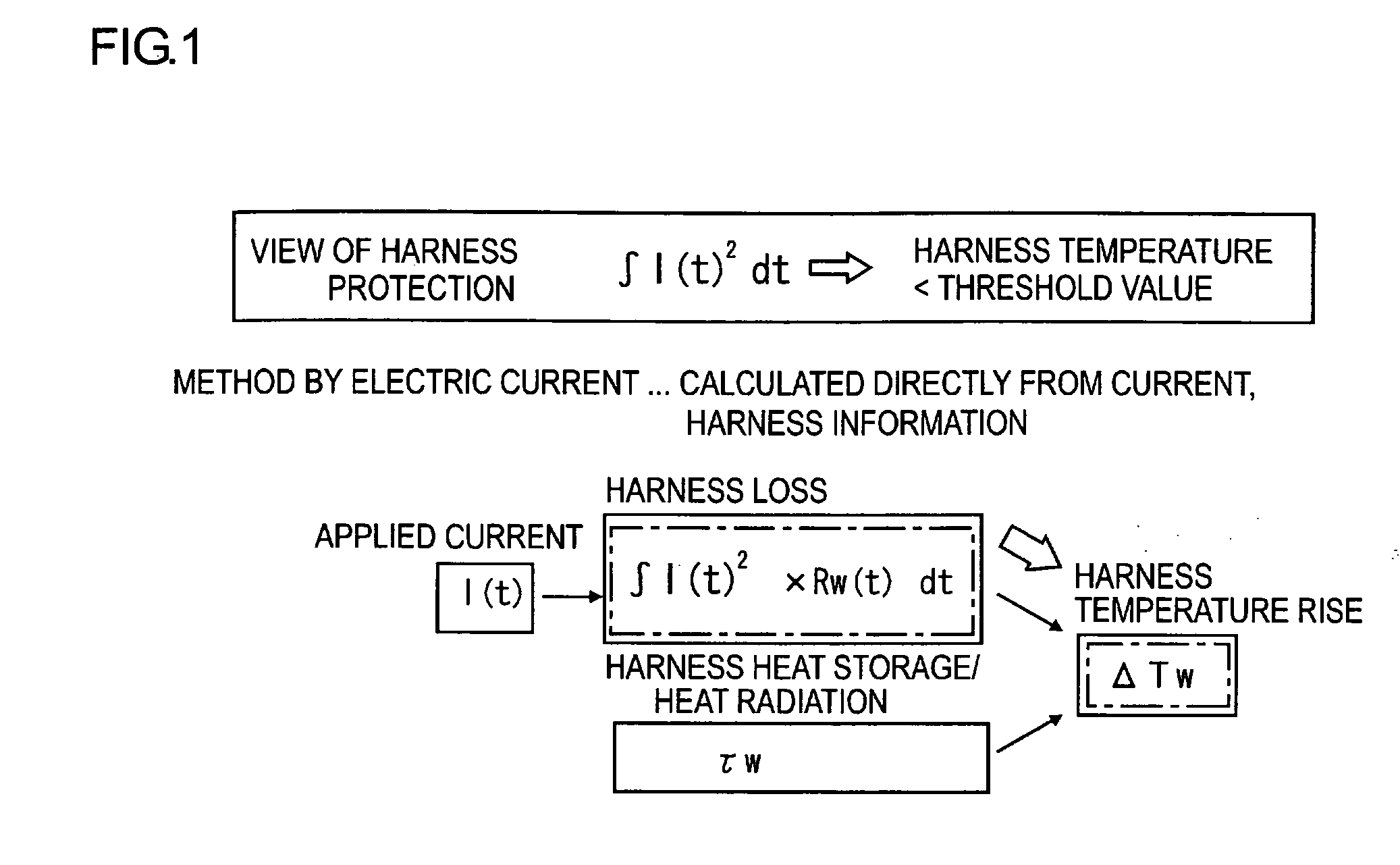
[0031]FIG. 1 is an explanatory view illustrating a concept of the wire (the wire harness) in accordance with the present invention. As illustrated in FIG. 1, in the present invention, a rise in temperature ΔTw in the harness is calculated directly from a loss of the harness due to an applied-current I, i.e. heat generation in the harness, and a heat-radiation time constant τw of the harness. Next, a temperature of the harness is estimated from the harness rise temperature ΔTw. This estimated harness temperature and a predetermined threshold value (an upper limit value) are compared, and then, when the harness temperature is equal to or higher than the predetermined threshold value, the applied-current I is broken...


PUM


Abstract

With a wire protection method in accordance with the present invention, the method being used for supplying electric power from a power source to a load, an applied-current to the load is detected every predetermined time, A wire rise temperature is calculated using the detected applied-current I(n) and by a relational expression concerning heat radiation and heat generation of the wire. The calculated rise in temperature is added to a reference temperature so that a wire temperature is estimated. When the estimated wire temperature is lower than a predetermined upper limit temperature, the calculation of the rise in temperature is repeated. When the estimated wire temperature has become equal to or higher than the predetermined upper limit temperature, the electric power supply from the power source to the load is stopped so that the wire is protected.

Description

TECHNICAL FIELD[0001]The present invention relates to wire protection methods and wire protection devices or, in particular, to a wire protection method and a wire protection device, the wire being used for supplying electric power from a power source to a load.BACKGROUND ART[0002]A vehicle wire harness could be deteriorated, or worn out, and allow a core wire thereof to have electrical contact with a body etc. and be short-circuited. Therefore, in order to protect smoking of the wire coating and a current control element (a switching element) due to such short-circuiting, a thermal fuse has conventionally been used. The thermal fuse detects an overheated state and breaks. However, as electric parts increase, use of such a thermal fuse has been arising a problem of maintaining a space for the thermal fuse to be mounted. Moreover, recovering after break requires replacing with a new thermal fuse, and thus maintenance is troublesome. Besides, in a case where current is repetitively ap...

Claims


Application Information

Patent Timeline
IPC IPC(8): H02H5/04
CPCG01K3/005G01K7/42H02H3/08H02H7/228H02H5/04H02H6/005
Inventor HIGUCHI, YUTAKATAKAHASHI, SEIJI
Owner AUTONETWORKS TECH LTD
Learn More