Electric power switching device and its abnormal test method

A power conversion device and abnormality detection technology, applied in emergency protection circuit devices, output power conversion devices, measurement devices, etc., can solve the problems of multiple IGBT components being damaged, unable to be protected, unable to protect, etc.

Inactive Publication Date: 2010-05-12
HITACHI LTD
View PDF1 Cites 8 Cited by
  • Summary
  • Abstract
  • Description
  • Claims
  • Application Information

AI Technical Summary

Problems solved by technology

[0008] However, in the conventional methods, the overcurrent is cut off by the IGBT itself, so when the current cutoff function is lost due to a failure of the IGBT itself, there is a problem that protection cannot be performed.
Furthermore, there is also a problem that the IGBT cannot be protected when wrong on / off control of the IGBT is performed due to a malfunction or failure of the gate drive circuit.
[0009] In addition, in a power conversion device composed of a plurality of IGBTs, a failure to cut off the current of one IGBT element causes an overcurrent of other IGBT elements, causing damage to multiple IGBT elements.

Method used


Image

  • Electric power switching device and its abnormal test method
  • Electric power switching device and its abnormal test method
  • Electric power switching device and its abnormal test method

Examples


Embodiment Construction

[0027] Hereinafter, an embodiment of the present invention will be described with reference to the drawings.

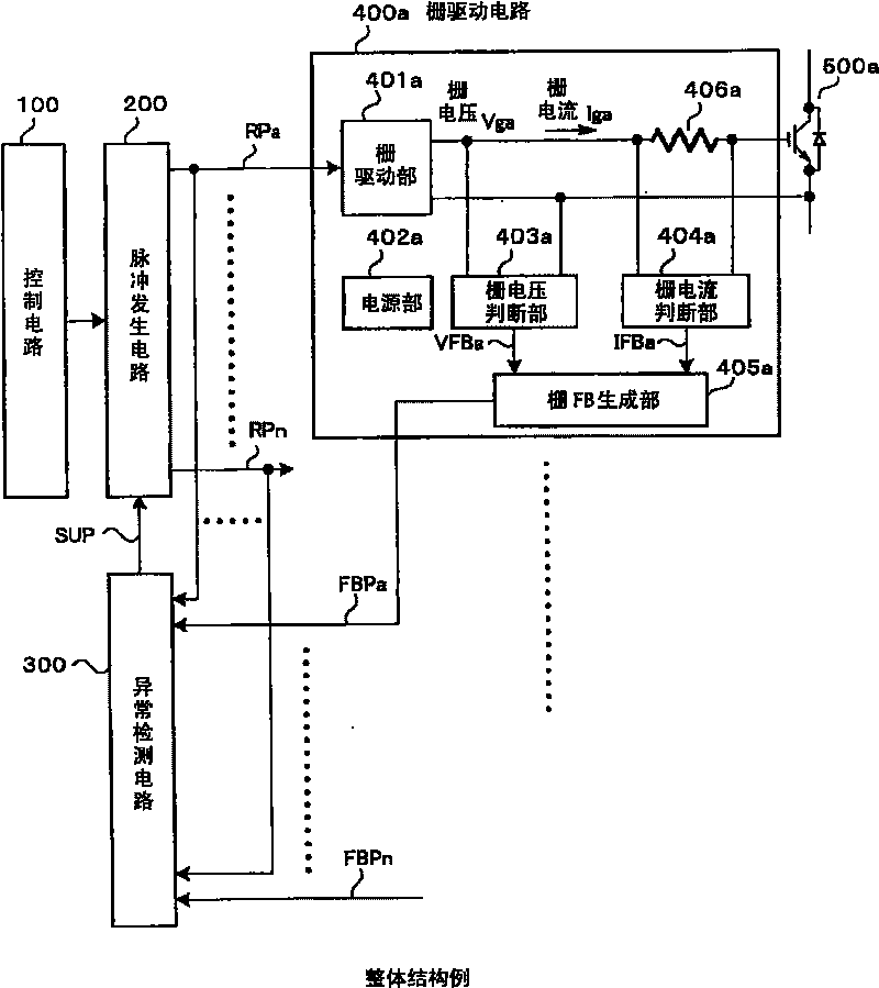
[0028] figure 1 It is a block diagram showing a configuration example of a power conversion device according to an embodiment of the present invention. control figure 1 , the overall structure of an embodiment of this example will be described.

[0029] This example has: a control circuit 100 for controlling the operation of the power conversion device; according to the instructions of the control circuit 100, a command pulse generating mechanism, namely a pulse generating circuit 200, which generates a command pulse for instructing the on / off of the IGBT; The command pulse, corresponding to the state of the command pulse, changes the magnitude of the gate voltage applied to the gate of the IGBT, thereby performing the gate drive mechanism for turning on or off the IGBT, that is, the gate drive circuit 400a; the IGBT element 500a; and Abnormality detection circuit ...


PUM


Abstract

To protect a power converter by detecting the abnormality of a gate driving circuit and the abnormality of an IGBT element certainly, in a power converter which is constituted of a plurality of IGBT elements. This power converter is composed of a control circuit 100, a pulse generating circuit 200 which generates command pulses to each IGBT, a plurality of gate driving circuits 400a-400n which control the ON-OFF action of the IGBTs, according to the inputted command pulses, IGBTs 500a-500n which are connected to each gate driving circuit, and an abnormality detecting circuit 300. The abnormality detecting circuit judges the disconformity between command pulses RPa-RPn and gate feedback signals FBPa-FBPn outputted from the gate driving circuits. In case that the disconformity state has continued for a certain time, the circuit judges it abnormal, and outputs a signal SUP to switch off all command pulses to the pulse generating circuit.

Description

[0001] This application is a divisional application of an invention application with a filing date of August 9, 2007 and an application number of 2007101407636. The invention and creation name of this application is a power conversion device and an abnormality detection method thereof. technical field [0002] The present invention relates to a power conversion device capable of controlling the conduction state by applying a voltage applied to a control input of the element and performing power conversion using a plurality of voltage-driven semiconductor elements, particularly having a device for detecting an abnormality of the voltage-driven semiconductor element A power conversion device of a mechanism and an abnormality detection method thereof. Background technique [0003] Insulated gate bipolar transistors (Insulated Gate Bipolar Transistor: IGBT) are representative of voltage-driven semiconductor devices, and are widely used in power conversion devices. Hereinafter, i...

Claims


Application Information

Patent Timeline
Patent Type & Authority Applications(China)
IPC IPC(8): H02M1/00H02M1/32
CPCG01R31/2607H02H7/1225H02M1/08H03K17/168
Inventor 松田敏彦小林清隆执行正谦
Owner HITACHI LTD
Why Eureka
Try Eureka