Flame detector

A flame detector and flame technology, used in instruments, alarms, fire alarms that rely on radiation, etc., can solve the problems of increasing the number of parts and reducing the productivity of flame detectors.

Inactive Publication Date: 2011-11-23
LIXIL NITTAN
View PDF2 Cites 0 Cited by
  • Summary
  • Abstract
  • Description
  • Claims
  • Application Information

AI Technical Summary

Problems solved by technology

This results in an increase in the number of parts and a decrease in flame detector productivity

Method used


Image

  • Flame detector
  • Flame detector
  • Flame detector

Examples


Embodiment Construction

[0049] (The overall structure of the flame detector)

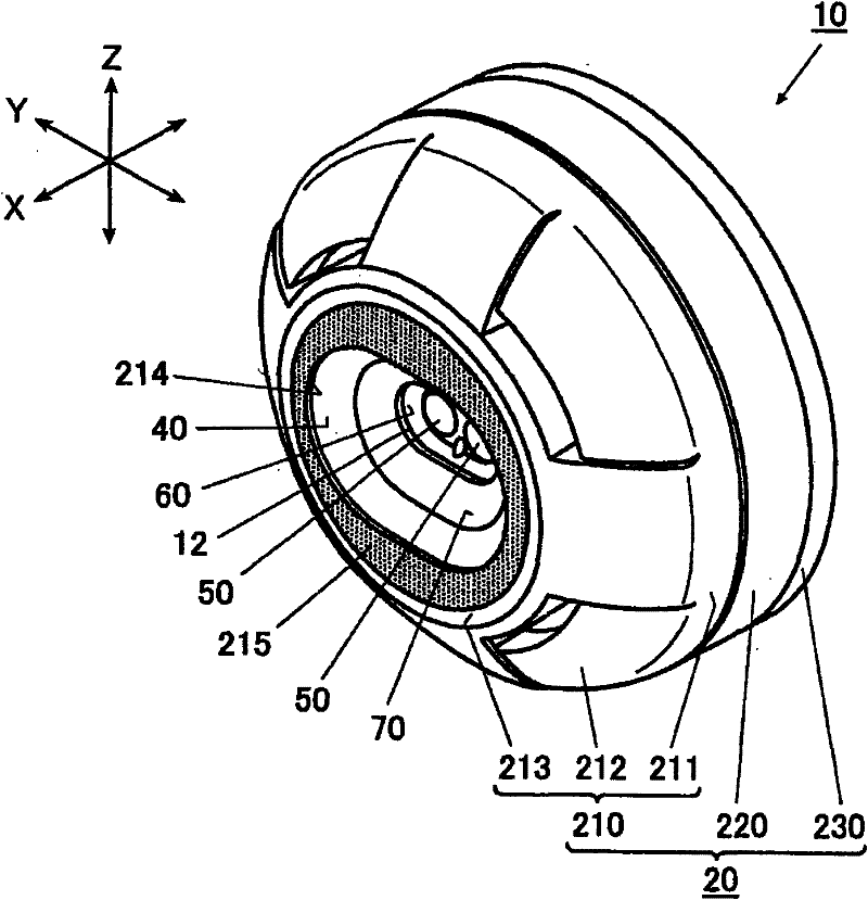
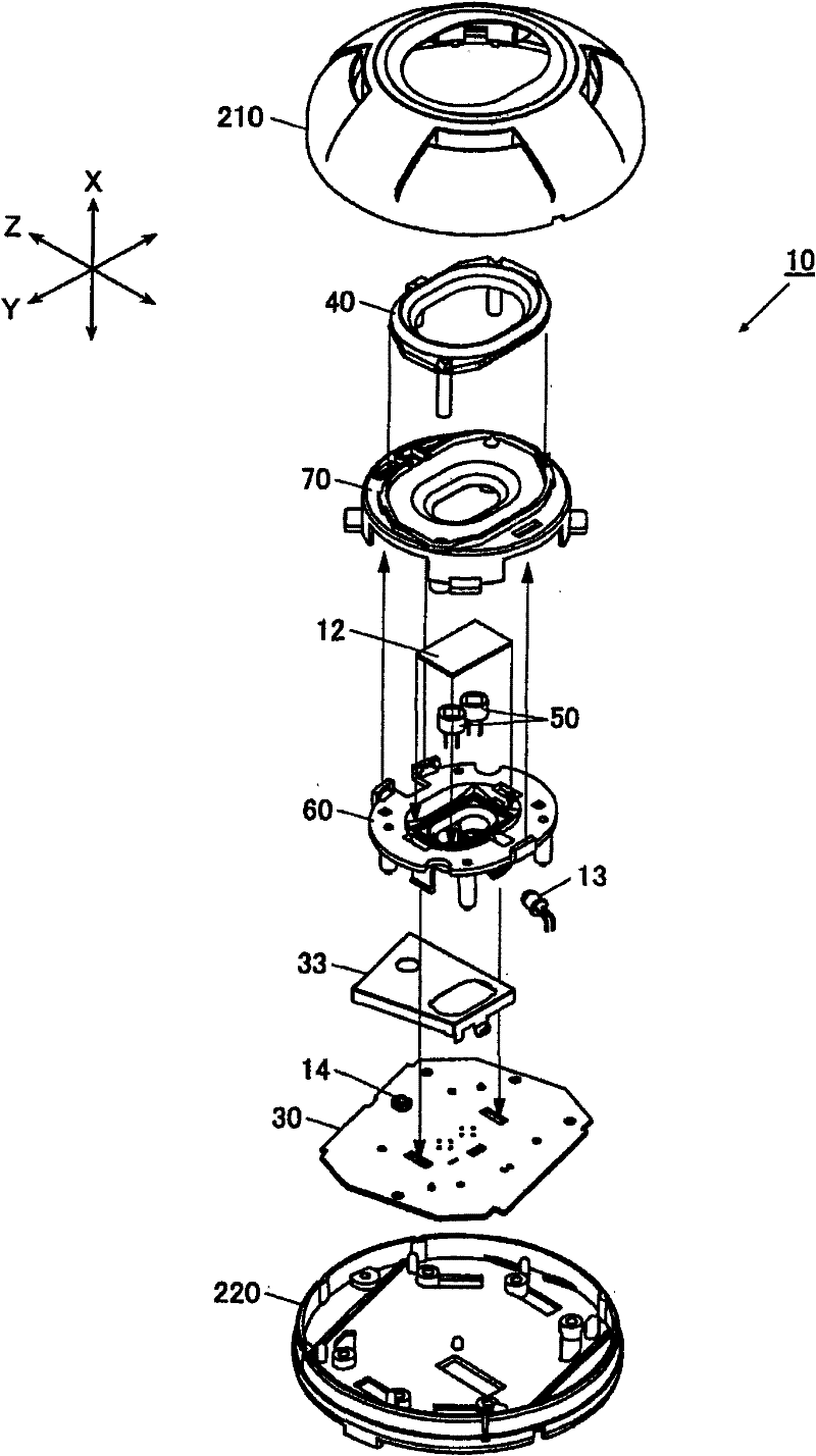
[0050] will refer to Figures 1 to 14B The flame detector 10 of the embodiment of the present invention is described. figure 1 is a perspective view of the flame detector 10, and figure 2 is its exploded perspective view.

[0051] Usually, the flame detector 10 is fixedly installed with its rear side upwards, and at the same time its front side remains downwards, for detecting fire in the area in front of its front side (that is, the lower area obtained in the installed state). flame. Such a flame detector 10 is connected to a receiver, not shown, which centrally handles a plurality of flame detectors arranged over the area to be monitored. At the time of flame detection, the flame detector sends a detection signal to the receiver.

[0052] In the following description, for the sake of convenience, the directions of the flame detector 10 are defined as follows. Specifically, the direction from the front side to the...


PUM


Abstract

A flame detector is provided. A circuit board is disposed in a housing. A first light source emits first light. A light guide member comprised of translucent material guides the first light from the first light source to a light emission portion of the light guide member. A first light receiving element detects second light having a predetermined wavelength unique to the flames. A second light source emits third light to a translucent cover which is disposed between an opening of the housing and the first light receiving element. A second light receiving element detects the third light passedthrough the translucent cover to test the translucency. The first light source, the second light source and the second light receiving element are mounted on the circuit board. The light emission portion is formed into a substantially annular shape which encloses the first light receiving element at a front side of the housing to limit a field of view of the first light receiving element to a predetermined range. And the light guide member has a light entrance portion and a light exit portion for the third light to form a light path from the second light source to the second light receiving element through the translucent cover and the light guide member.

Description

[0001] The entire disclosure of Japanese Patent Application No. 2008-241097 filed on September 19, 2008 including specification, drawings and claims is hereby incorporated by reference. technical field [0002] The present invention relates to a flame detector that performs detection of flames by acquiring light having a wavelength specific to flames. Background technique [0003] A flame detector of the related art has a main detection light receiving element which receives infrared radiation from a front hole of a housing to thereby detect a flame; A transmission plate for transmission is made; a test light source, which illuminates test light for detecting stains on the light receiving window; a test light receiving element, which receives the test light passing through the light receiving window, to thereby determine the test light on the light receiving window. the degree of stains on the element; and an operation indicator light, which lights up at the front side of th...

Claims


Application Information

Patent Timeline
Patent Type & Authority Patents(China)
IPC IPC(8): G08B17/12
CPCG08B17/12G08B29/08
Inventor 工藤彰久桜井和羲金子宏秋山信幸片桐正浩
Owner LIXIL NITTAN
Why Eureka
Try Eureka