Laser scanning sensor test system and test method

A laser scanning and testing system technology, applied in electronic circuit testing, printed circuit testing, instruments, etc., can solve the problems of inhibiting production speed, time-consuming and laborious, false detection, etc., and achieve the effect of improving production speed

Active Publication Date: 2019-12-03
广东兴颂科技有限公司
View PDF7 Cites 0 Cited by
  • Summary
  • Abstract
  • Description
  • Claims
  • Application Information

AI Technical Summary

Problems solved by technology

[0003] The existing method of detecting whether a circuit board is a defective product is often manually determined by the staff, which is not only time-consuming and laborious, but also may cause false detection due to the negligence of the staff itself, and greatly inhibits the production speed

Method used


Image

  • Laser scanning sensor test system and test method
  • Laser scanning sensor test system and test method

Examples


Embodiment approach

[0068] As a preferred embodiment of the present invention, the test method also includes:

[0069] After judging that the circuit boards of the system are all normal products, the communication function of the laser scanning sensor is detected through the configuration software on the PC side, and the abnormal communication function of the laser scanning sensor is displayed through the configuration software. The communication function includes RS232 communication module, Running information of RS485 communication module and Can communication module.

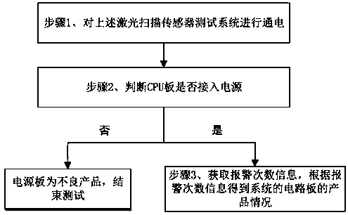
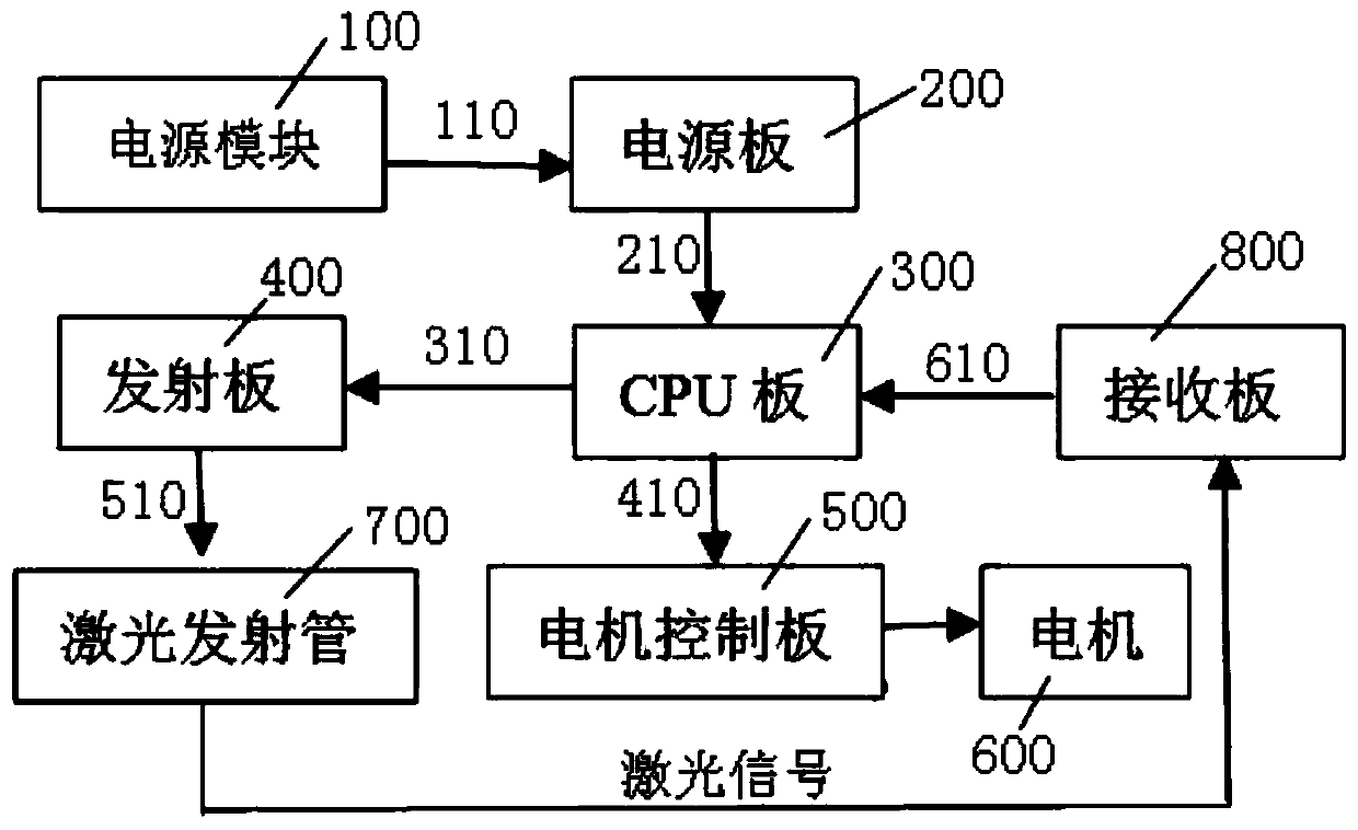
[0070] When working, first connect the above-mentioned circuit board and fix it on the test frame through connecting wires and probes, and then power on to simulate laser operation. As long as there is an error in one step during the power-on test, the entire laser system will not operate normally, the motor 600 will stop running, and the indicator light of the CPU board 300 will report a corresponding error. Specifically, when...


PUM


Abstract

The invention relates to a laser scanning sensor test system and test method. The method comprises the following steps: step 1, carrying out electrification on a laser scanning sensor test system; step 2, determining whether a CPU board is connected to a power supply; if not, indicating that a power supply board is a defective product, ending the test; and if so, performing step 3; and step 3, acquiring alarm frequency information and acquiring the product condition of the circuit board of the system according to the alarm frequency information. According to the invention, with the laser scanning sensor test system and test method, the abnormal condition of the circuit board of the laser scanner can be accurately detected through the obtained alarm times, so that the production speed is greatly increased. The laser scanning sensor test system and test method can be applied to the field of laser scanning sensors.

Description

technical field [0001] The invention relates to the field of laser scanning sensors, in particular to a laser scanning sensor testing system and testing method. Background technique [0002] In the industrial field, laser sensors are more and more widely used. Due to the complexity of laser scanning sensors, circuit boards may have virtual soldering during the placement process, and products with virtual soldering will have abnormal functions and become defective products. , need to be detected. [0003] The existing method of detecting whether a circuit board is a defective product is often manually measured by the staff, which is not only time-consuming and laborious, but also may cause false detection due to the negligence of the staff itself, and greatly inhibits the production speed. [0004] The laser scanner that contains 5 circuit boards is commonly used in the existing laser scanner, and these 5 circuit boards are CPU board, power supply board, transmitting board, ...

Claims


Application Information

Patent Timeline
Patent Type & Authority Applications(China)
IPC IPC(8): G01R31/28G08B21/18
CPCG01R31/2801G01R31/2829G01R31/2815G08B21/185
Inventor 胡连逵周剑刘沛亮
Owner 广东兴颂科技有限公司
Why Eureka
Try Eureka