Exhaust gas evacuation device for internal combustion engine

A technology of exhaust device and internal combustion engine, which is applied in the direction of exhaust device, diagnosis device of exhaust gas treatment device, internal combustion piston engine, etc., can solve the problem of not judging the regeneration period and so on.

Inactive Publication Date: 2013-04-03
TOYOTA JIDOSHA KK
View PDF5 Cites 0 Cited by
  • Summary
  • Abstract
  • Description
  • Claims
  • Application Information

AI Technical Summary

Problems solved by technology

[0004] In the device disclosed in Patent Document 2, in order to perform the regeneration process of burning the filter that traps PM, the time to perform the regeneration process is judged based on the exhaust pressure on the upstream side of the filter. However, the temperature of the exhaust gas varies over time. When the rate is negative, the regeneration period is not judged

Method used


Image

  • Exhaust gas evacuation device for internal combustion engine
  • Exhaust gas evacuation device for internal combustion engine
  • Exhaust gas evacuation device for internal combustion engine

Examples


Embodiment Construction

[0038]

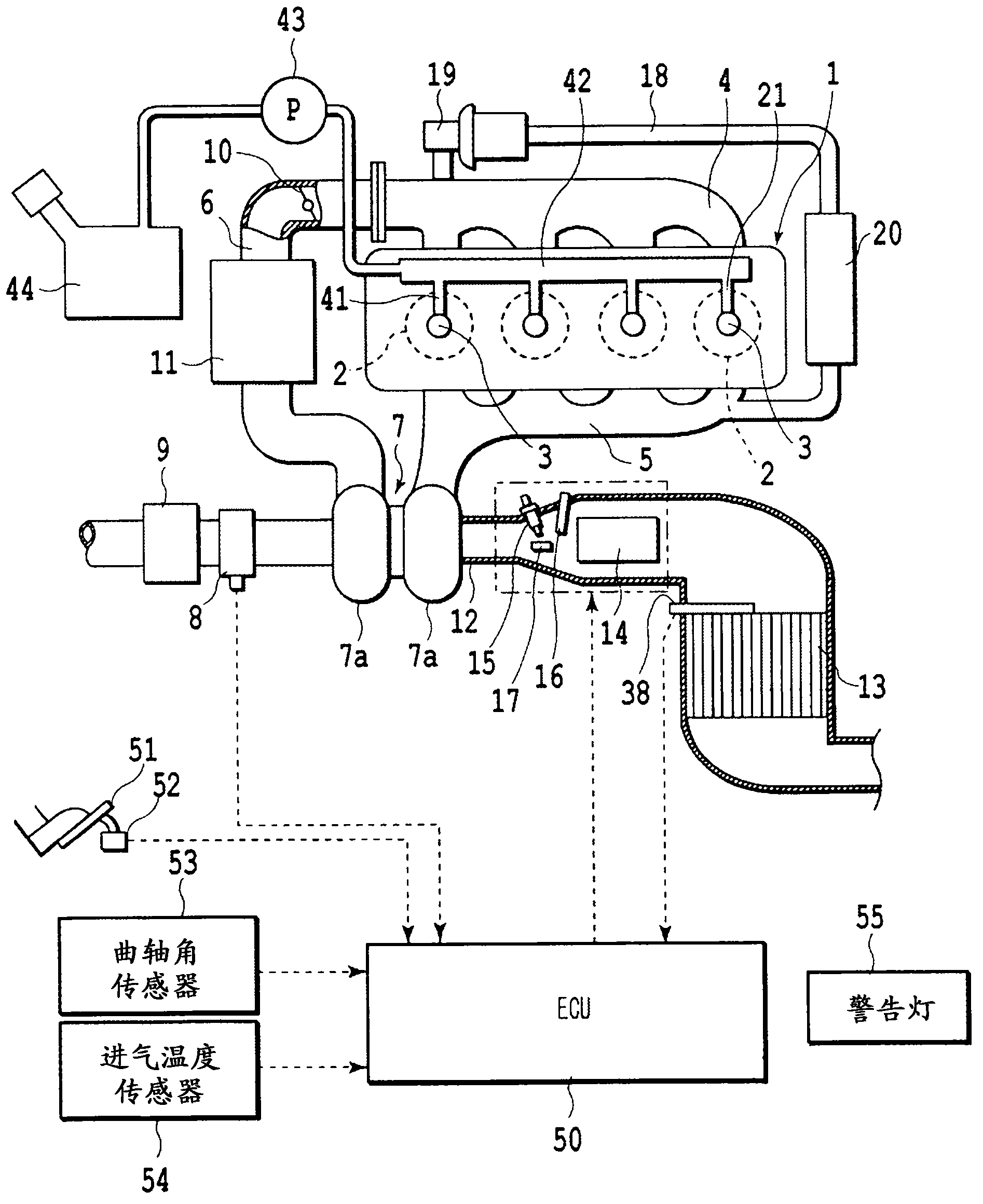
[0039] Next, preferred embodiments of the present invention will be described in detail. figure 1 The first embodiment of the present invention is shown. exist figure 1 In the above, the engine body 1 is a compression ignition internal combustion engine (diesel engine) fueled by light oil, but it may also be other types of internal combustion engines. The engine block 1 has a combustion chamber 2 in each of four cylinders. An electronically controlled injector 3 for injecting fuel is arranged in each combustion chamber 2 . An intake manifold 4 and an exhaust manifold 5 are connected to the combustion chamber 2 . The intake manifold 4 is connected to an outlet of a compressor 7 a of an exhaust turbocharger 7 via an intake pipe 6 , and an inlet of the compressor 7 a is connected to an air filter 9 via an air flow meter 8 . The upstream side of the air cleaner 9 is open to the atmosphere.

[0040] A throttle valve 10 driven by a stepping motor is arranged in the i...


PUM


Abstract

An exhaust gas evacuation device for an internal combustion engine is provided with: a burner device (40) which is provided with a fuel addition device (15) for adding fuel to the exhaust gas evacuation path (12) of the internal combustion engine (1) and which combusts the added fuel; and a controller (50) which detects an abnormality of the burner device (40) on the basis of a variation in the temperature at a temperature detection point within the exhaust gas evacuation path (12) after the amount of addition of the fuel is changed, the temperature detection point being located on the downstream side of the fuel addition device (15).

Description

technical field [0001] The present invention relates to an exhaust device capable of adding fuel to an exhaust passage of an internal combustion engine, the exhaust device having a function of detecting an abnormality. Background technique [0002] In order to detect the accumulation amount of PM (Particulate Matter: Particulate Matter) accumulated in the exhaust passage of the internal combustion engine, various proposals have been made. [0003] In the device disclosed in Patent Document 1, each of the plurality of particulate matter sensors provided in the exhaust passage has a heater for combusting and removing PM deposited on the plurality of particulate matter sensors. An abnormality of the particulate matter sensor can be detected by comparing the time required for the regeneration of the plurality of particulate matter sensors. [0004] In the device disclosed in Patent Document 2, in order to perform the regeneration process of burning the filter that traps PM, the...

Claims


Application Information

Patent Timeline
IPC IPC(8): F01N3/02F01N3/20
CPCF01N2610/102F01N2900/1404F01N2430/085F01N2550/05F01N3/0256F02D41/1446F01N2560/06F02P19/026F01N2430/06F01N11/002Y02T10/47F01N3/106F02B37/00Y02T10/40
Inventor 羽岛孝志
Owner TOYOTA JIDOSHA KK
Why Eureka
Try Eureka