
Sealing contraction of gear case
A technology of sealing structure and gear box, which is applied in the direction of manufacturing tools, metal processing, sawing equipment, etc., can solve the problems of downward flow of grease oil and insufficient lubrication, and achieve the effect of increasing the cutting volume
- Summary
- Abstract
- Description
- Claims
- Application Information
AI Technical Summary
Problems solved by technology
Method used
Image

Examples
Embodiment Construction
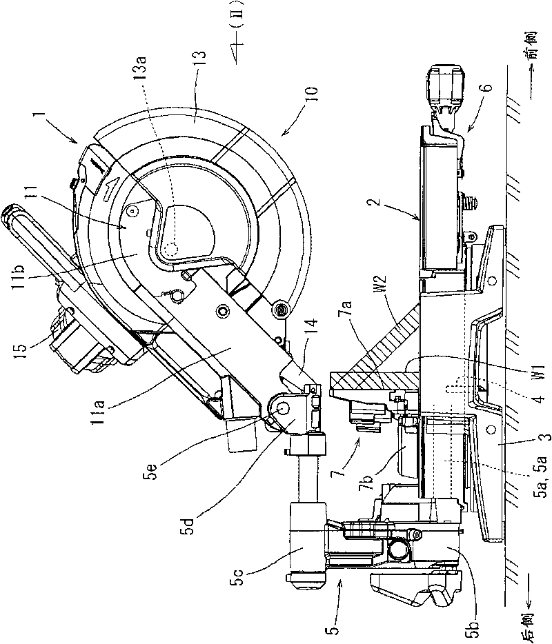
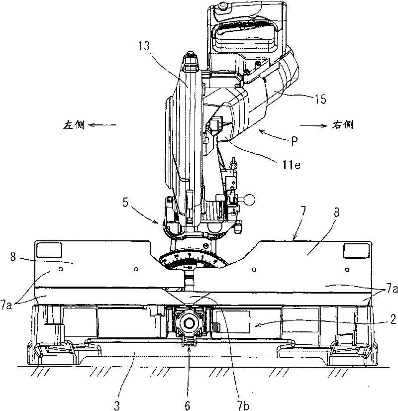
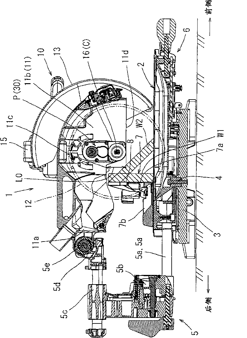
[0025] Below, refer to Figure 1 to Figure 5 Specific embodiments of the present invention will be described. figure 1 The whole desktop cutting machine 1 which has the sealing structure of this embodiment is shown. In the present embodiment, a so-called sliding table cutter is exemplified as the table cutter 1 . figure 1 In , the user operates the desktop cutting machine 1 on the right side of the figure. In the following description, the side closer to the user ( figure 1 the middle right side) as the front side, and the side away from the user ( figure 1 middle left) as the rear side. In addition, if figure 2 As shown, left and right are based on the user, when the user stands in front of the desktop cutting machine 1 .
[0026] The desktop cutting machine 1 has: a workbench 2 for supporting the pieces W1 and W2 to be cut; a base 3 supporting the workbench 2 in a horizontally rotatable state; Fuselage supporting part 5 on platform 2. The table 2 is supported on the...
PUM
 Abstract
Description
Claims
Application Information