Multistage rotary compressor

Inactive Publication Date: 2005-09-29
SANYO ELECTRIC CO LTD
View PDF8 Cites 3 Cited by
  • Summary
  • Abstract
  • Description
  • Claims
  • Application Information

AI Technical Summary

Benefits of technology

[0012] The present invention was made to solve such a problem in a conventional multistage rotary compressor and the object of the present invention is to provide a m

Problems solved by technology

However, the level of the oil surface in the oil reservoir at a bottom portion of the closed vessel A cannot be made at a higher position than the cover plate R. If the level of the oil surface in the oil reservoir exceeds the cover plate R, oil flows into the oil reservoir from an outlet of a passage (not shown) for discharging the intermediate pressure refrigerant gas compressed by the low stage side rotary compressing element into the closed v

Method used


Image

  • Multistage rotary compressor
  • Multistage rotary compressor
  • Multistage rotary compressor

Examples


Example

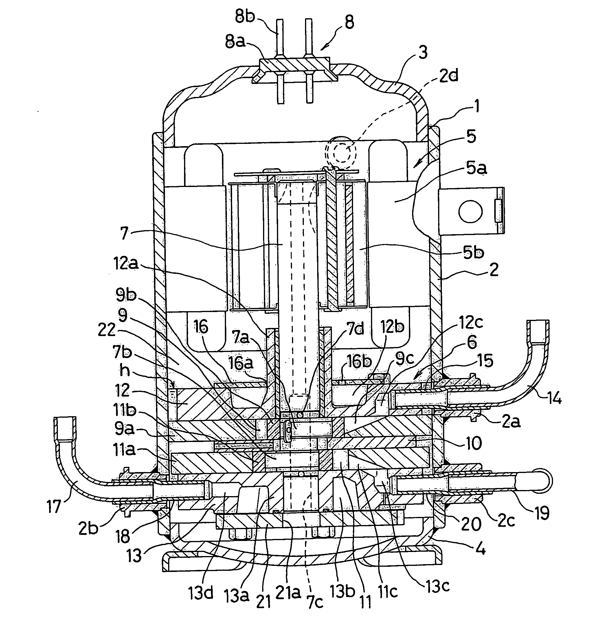
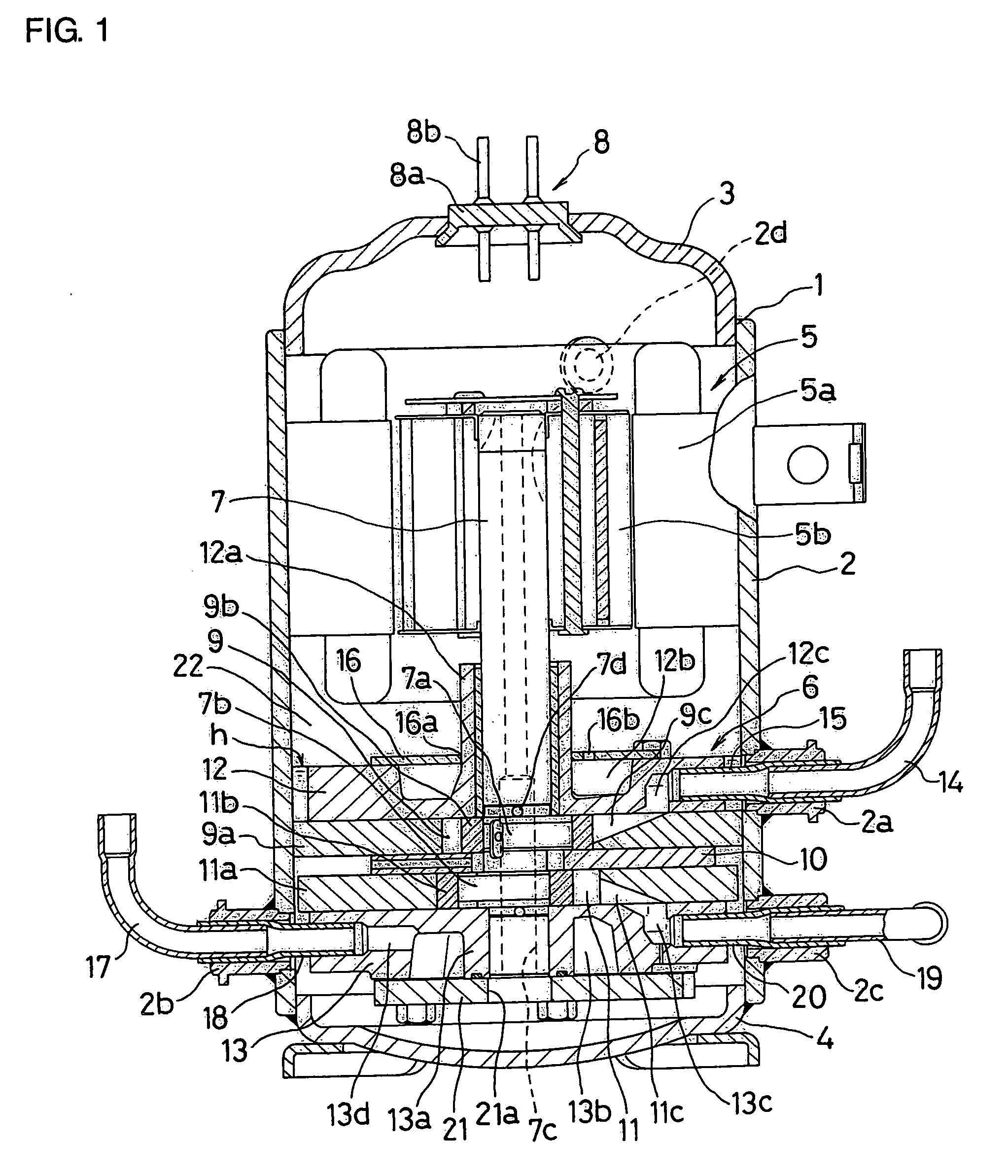
[0025] First, a first embodiment of the present invention shown in FIG. 1 will be described. The reference numeral 1 is a closed vessel. The closed vessel 1 is comprised of a cylindrical vessel 2 and end caps 3, 4 attached to opening end portions of the vessel 2, and is provided in such a manner that a motor-operating element 5 and a rotary compressing element 6 are positioned at upper and lower portions in this closed vessel 1 respectively.

[0026] The motor-operating element 5 is comprised of an annular stator 5a fixed to an inner surface of the vessel 2 and a rotor 5b, which rotates inside the stator 5a. The rotor 5b is journalled to an upper end portion of a rotating shaft 7. This motor-operating element 5 rotates the rotor 5b by feed to the stator 5a through a terminal 8 attached to the end cap 3.

[0027] The terminal 8 is comprised of a base 8a fixed to an mounting hole of the end cap 3 and a plurality of connecting terminals 8b provided on the base 8a while penetrating through ...

Example

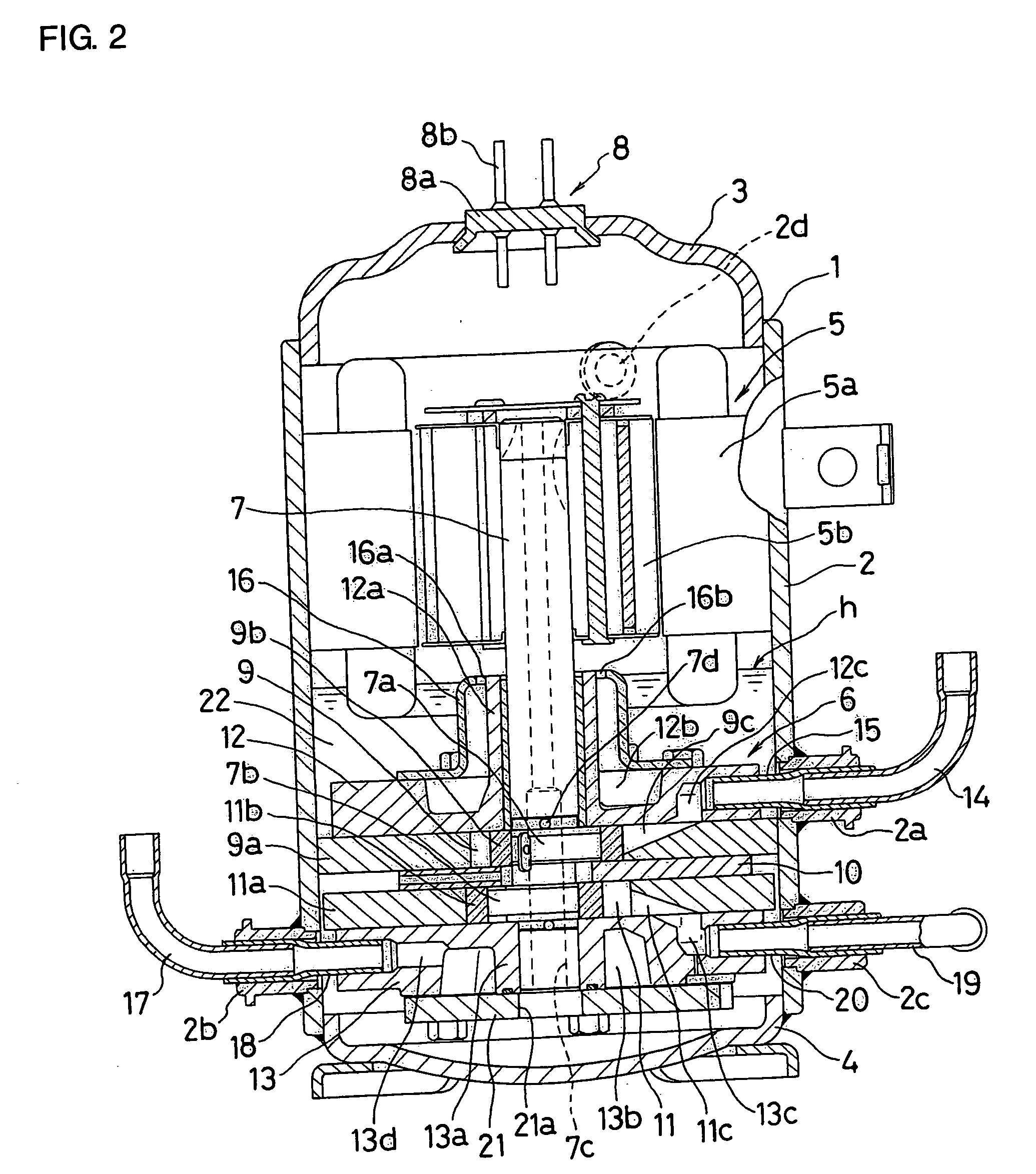
[0042] Next, a second embodiment shown in FIG. 2 will be described. In the second embodiment the components corresponding to the above-mentioned first embodiment are denoted by the same reference numerals as described above.

[0043] In FIG. 2, the reference numeral 1 is a closed vessel. The closed vessel 1 is comprised of a vessel 2 formed into a substantially cylindrical shape and end caps 3, 4 attached to opening end portions of the vessel 2, and is provided in such a manner that a motor-operating element 5 and a rotary compressing element 6 are positioned at upper and lower portions in this closed vessel 1 respectively.

[0044] The motor-operating element 5 is comprised of an annular stator 5a fixed to an inner surface of the vessel 2 and a rotor 5b, which rotates inside the stator 5a. The rotor 5b is journalled to an upper end portion of a rotating shaft 7. This motor-operating element 5 rotates the rotor 5b by feed to the stator 5a through a terminal 8 attached to the end cap 3. ...

Example

[0061] Next, a third embodiment shown in FIG. 3 will be described. In the third embodiment the components (which contain substantially the same components even if their positions are different) corresponding to the above-mentioned first embodiment or second embodiment are denoted by the same reference numerals as described above.

[0062] In FIG. 3, the reference numeral 1 is a closed vessel. The closed vessel 1 is comprised of a vessel 2 into a substantially cylindrical shape and end caps 3, 4 attached to opening end portions of the vessel 2, and is provided in such a manner that a motor-operating element 5 and a rotary compressing element 6 are positioned at upper and lower portions in this closed vessel 1 respectively.

[0063] The motor-operating element 5 is comprised of an annular stator 5a fixed to an inner surface of the vessel 2 and a rotor 5b, which rotates inside the stator 5a. The rotor 5b is journalled to an upper end portion of a rotating shaft 7. This motor-operating elem...


PUM

PropertyMeasurementUnit
Pressureaaaaaaaaaa
Diameteraaaaaaaaaa
Dimensionaaaaaaaaaa

Abstract

The present invention relates to a multistage rotary compressor. In the multistage rotary compressor, a motor-operating element 5 and a rotary compressing element 6 are provided at upper and lower portions in a closed vessel 1. In the rotary compressing element 6, a low stage side rotary compressing element 9 and a high stage side rotary compressing element 11 are positioned on the upper and lower sides respectively. An upper supporting member 12 is attached onto the low stage side rotary compressing element 9, and a substantially cup-shaped cover material 16 is attached onto the upper supporting member 12 to close an opening surface of a muffling chamber 12b formed in the upper supporting member 12. The substantially cup-shaped cover material 16 is formed in a high dimension so that the upper end of the cover material 16 is positioned at an upper end or near an upper end of a bearing portion 12a formed in the upper supporting member 12. Further, a discharge hole 16b for discharging a refrigerant gas is provided in the upper end surface of the cover material 16 near an outer diameter portion of the bearing portion 12a. Consequently, the level h of the oil surface for oil filled in the closed vessel 1 can be set so as to be near the upper end of the cover material 16. According to the present invention, the amount of oil filled in the closed vessel can be increased and the oil separation in the closed vessel can be efficiently made.

Description

BACKGROUND OF THE INVENTION [0001] 1. Field of the Invention [0002] The present invention relates to a multistage rotary compressor, and more specifically it relates to a multistage rotary compressor that can increase the amount of oil filled into a closed vessel and can efficiently make oil separation in the closed vessel. [0003] 2. Description of the Related Art [0004] A multistage rotary compressor including a motor-operating element and a rotary compressing element driven by this motor-operating element disposed in a closed vessel has been known. For example, a two-stage rotary compressor shown in FIG. 4 will be described. In FIG. 4, an upper portion in a closed vessel A is provided with a motor-operating element B composed of a stator and a rotor, the rotor is journalled to an upper end portion of a rotating shaft C, a lower portion in the closed vessel A is provided with a rotary compressing element G composed of a low stage side rotary compressing element E and a high stage s...

Claims


Application Information

Patent Timeline
IPC IPC(8): F04B17/00F04B39/00F04C18/356F04C23/00F04C29/00F04C29/02F04C29/06F04D17/12F04D29/00
CPCF01C21/108F04C18/3564F04C23/001F04C23/008F04C29/068F04C29/02F04C29/028F04C29/065F04C29/0092A47L13/16B32B5/18B32B27/36
Inventor SATO, KAZUYA
Owner SANYO ELECTRIC CO LTD
Why Eureka
Try Eureka