
Elastic buffering feeding device of inner diameter slicing machine and feeding method thereof

A technology of elastic buffering and inner circle slicing, applied in stone processing tools, manufacturing tools, stone processing equipment, etc., can solve the problem of low cutting speed, and achieve the effect of ensuring safe cutting, improving adaptability and increasing cutting speed.

Inactive Publication Date: 2012-07-18
杨潇
View PDF0 Cites 0 Cited by
  • Summary
  • Abstract
  • Description
  • Claims
  • Application Information

AI Technical Summary

Problems solved by technology

[0016] The stepper motor works in a rigid connection mode, and it is rigid to give force. The step amount of each step is applied to the cutting edge of the incision slicer. In practice, there are the following shortcomings: when the stepping feed speed is set relatively low, the two The working conditions of the workers are basically similar, and the cutting speed (cutting area per unit time) is relatively low under such working conditions, which is 15-30% lower than the manual cutting speed on average; There are a large number of slicers, and all parameters are taken within a relatively safe and conservative range. Compared with manual slicers, the cutting speed is about 20% lower

Method used


Image

  • Elastic buffering feeding device of inner diameter slicing machine and feeding method thereof
  • Elastic buffering feeding device of inner diameter slicing machine and feeding method thereof
  • Elastic buffering feeding device of inner diameter slicing machine and feeding method thereof

Examples


Embodiment 1

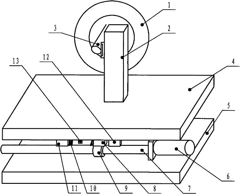
[0045] Embodiment one: figure 1 As shown, this embodiment includes a cutting tool 1 driven by a main motor, an X-axis mobile table 4 driven by a stepping motor 6, and a Y-axis mobile table 5 driven by a stepping motor. The X-axis mobile table 4 is arranged on the Y-axis Above the movable workbench 5, the X-axis movable workbench 4 is provided with a clamping frame 2, and a spring 10 is arranged in the connection device for controlling displacement and force between the X-axis movable workbench 4 and the Y-axis movable workbench 5 . The control transmission connection device of described displacement and force comprises stepper motor 6, and stepper motor 6 is provided with lead screw 7, and lead screw nut 9 is sleeved on lead screw 7, and stepper motor 6 is fixedly installed on the Y-axis mobile work. On the platform 5, the lead screw nut 9 is provided with a load-bearing block 8, one side of the load-bearing block 8 is connected with a spring 10, and one end of the spring 10 ...

Embodiment 2

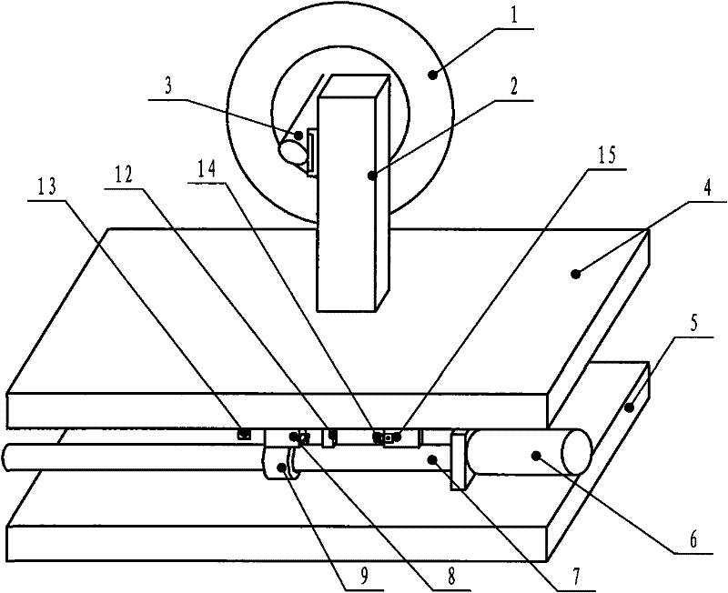
[0050] Embodiment two: figure 2 As shown, the spring of this embodiment is a tension spring 14, and the tension spring 14 is arranged between the load-bearing block and the adjustment piece 15, the stopper 12 and the adjustment piece 15 are fixed on the upper workbench, and the stopper 12 is arranged on the load-bearing Between the block and the adjusting member 15, the extension spring 14 is fixed on the adjusting member 15, and the adjusting member 15 is provided with an adjusting device for adjusting the elastic force of the extension spring (for prior art, so its structural description is omitted), other structures and embodiments One is the same.

[0051] Parameter range of tension spring: compression 1-10 mm, withstand force change of 10 kg. Generally, in the natural static state without cutting, the force of the tension spring is about 0.1 kg; under the condition of maximum force (generally no more than 10 kg), the deformation of the tension spring is 4 mm. Control s...

Embodiment 3

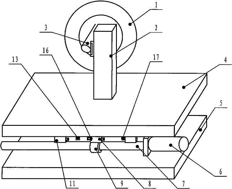
[0052] Embodiment three: image 3 As shown, both sides of the lead screw nut 9 and the bearing block 8 of the present embodiment are provided with tension springs 17 and stoppers, and the stoppers are all fixed on the upper workbench, and the bearing block is also provided with a vibration sensor 16, The limit switch 13 is arranged on the upper workbench, and the limit switch 13 can slide left and right on the upper workbench, that is, an extension spring is respectively connected to both sides of the load-bearing block, and each extension spring is connected with a respective stopper. The structure is the same as the first embodiment.


PUM

PropertyMeasurementUnit
lengthaaaaaaaaaa

Abstract

An elastic buffering feeding device of an inner diameter slicing machine belongs to the device of automatic inner diameter slicing machines. The feeding device comprises a cutting tool driven by a main shaft motor, an X axis travelling table driven by a stepping motor and a Y axis travelling table driven by the stepping motor. The X axis travelling table is arranged above the Y axis travelling table, and a frame for chucking materials is arranged on the X axis travelling table. The present invention is characterized in that an elastic part or an elastic assembly is arranged in a delivery connecting device for controlling shift and force, arranged between the X axis travelling table and the Y axis travelling table. Control feed instantly completed is absorbed by the elastic part or the elastic assembly, so the purpose in elastically buffering feeding force is achieved. The defect that the pulse feeding is directly forced is overcome, the influence of part rigidity variation of cutting materials on cutting quality and cutting efficiency is avoided, and the adoptability of processing parameters to the cutting possibility of materials cut is improved. Thus, cutting speed is improved.

Description

Technical field: [0001] The invention belongs to a device of an automatic inner circle slicer, and in particular relates to a feeding device and a feeding method of the automatic inner circle slicer. Background technique: [0002] The inner circle slicer is the most commonly used processing equipment in the plane cutting of sintered NdFeB rare earth permanent magnet materials. It includes a semi-automatic inner circle slicer, a fully automatic inner circle slicer, a fully automatic inner circle slicer including a microcomputer control system, a cutting tool driven by a main motor, and a feeding device. The feeding device includes an X-axis movement driven by a stepping motor. The worktable, the Y-axis movable worktable driven by the stepping motor, the X-axis movable worktable is arranged above the Y-axis movable worktable, and the stepping motor driving the X-axis movable worktable is arranged on the X-axis movable workbench. [0003] In the traditional manual control cutt...

Claims


Application Information

Patent Timeline
Patent Type & Authority Patents(China)
IPC IPC(8): B28D1/24
Inventor 杨潇
Owner 杨潇
Learn More