Method for measuring rotor speed of turbo generator and device thereof

A steam turbine generator, rotor speed technology, applied in the measurement device, linear/angular velocity measurement, velocity/acceleration/impact measurement and other directions, can solve the problems of large measurement error, general signal-to-noise ratio, etc., to achieve small linear error and rotational speed. The effect of small measurement error

Active Publication Date: 2011-09-07
ELECTRIC POWER RES INST OF GUANGDONG POWER GRID
View PDF0 Cites 0 Cited by
  • Summary
  • Abstract
  • Description
  • Claims
  • Application Information

AI Technical Summary

Problems solved by technology

The measurement range of the measuring device of the prior art 2 is 0-5000Hz, and the output is 0-5V. After analysis, the measuring device is affected by white noise, and there is an interference wave of 20mv, which is equivalent to 20r / min. The frequency range of the load rejection test (2750~3250Hz) has an average signal-to-noise ratio and large measurement errors

Method used


Image

  • Method for measuring rotor speed of turbo generator and device thereof
  • Method for measuring rotor speed of turbo generator and device thereof
  • Method for measuring rotor speed of turbo generator and device thereof

Examples


Embodiment Construction

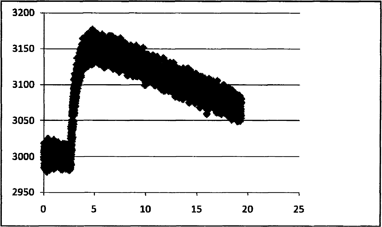
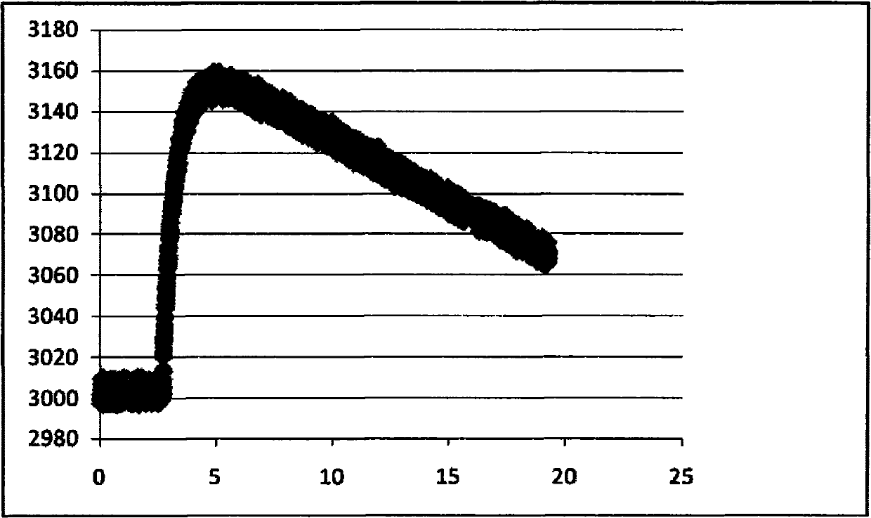
[0029] The method and device for measuring the rotor speed of the turbogenerator of the present invention can measure the pulse electric signal according to the Carry out F / V conversion, that is, perform F / V conversion on the pulse electric signal in stages, compared with the prior art 2 according to U(f)=f×k 1 For voltage signals that are converted in a linear form (such as Figure 11 ), since the slope k>k 1 , then the frequency range corresponding to the converted voltage signal within the predetermined range is relatively small, and the resulting linear error is relatively small, and it is not easily affected by interference waves, and the rotational speed measurement error is relatively small.

[0030] The specific embodiments of the present invention will be described in detail below in conjunction with the accompanying drawings.

[0031] The method for measuring the rotor speed of the turbogenerator of the present invention, such as Figure 5 , including the steps: ...


PUM


Abstract

The invention discloses a method for measuring the rotor speed of a turbo generator and a device thereof. The method comprises the following steps: converting the rotor speed into a pulse electrical signal through a sensor; carrying out F / V conversion on the pulse electrical signal, wherein U(f) refers to the converted voltage signal, f refers to the pulse electrical signal, f1 and f2 refer to two predetermined pulse electrical signal values, Umax refers to a predetermined voltage value; carrying digital-to-analogue conversion on the voltage signal after the F / V conversion; and converting the voltage signal after the F / V conversion into digital quantity through a data acquisition unit. In the method, F / V conversion is carried out on the pulse electrical signals by stages, with respect to the voltage signal which is converted according to the U(f) = f*k1 linear form in prior art 2, because k is more than k1, the frequency range corresponding to the converted voltage signal in the predetermined scope is small, and the caused linear error is also small, the measurement is insusceptible to interference wave, and the measurement error of the rotor speed is small.

Description

technical field [0001] The invention relates to a steam turbine generator, in particular to a method and a device for measuring the rotational speed of a turbine generator rotor. Background technique [0002] Many measuring devices for the rotor speed of turbogenerators are realized by sensors, F / V (frequency / voltage, frequency / voltage) conversion units, and data collectors. When the rotor rotates, the sensor converts the rotor speed into a pulse electrical signal, which is converted into a voltage signal by the F / V conversion unit, and then the voltage signal is converted into a digital quantity by the data collector to complete the measurement of the turbine generator rotor speed. [0003] In the load shedding test of the steam turbine generator set, the rotor speed changes very rapidly, and the rotor speed can reach 280-400r / min within 40-110ms of initial soaring, which has high requirements for the measurement accuracy and response speed of the rotor speed. Analysis It ...

Claims


Application Information

Patent Timeline
Patent Type & Authority Patents(China)
IPC IPC(8): G01P3/00
Inventor 田丰
Owner ELECTRIC POWER RES INST OF GUANGDONG POWER GRID
Why Eureka
Try Eureka