An optical fiber sensor probe

An optical fiber sensing probe and optical fiber technology, applied in the field of sensing probes, can solve the problems of small frequency range, low signal-to-noise ratio, easy to be affected by changes in light source intensity and environmental temperature changes, etc. lower effect

Inactive Publication Date: 2018-07-27
NO 49 INST CHINESE ELECTRONICS SCI & TECH GRP +1
View PDF11 Cites 0 Cited by
  • Summary
  • Abstract
  • Description
  • Claims
  • Application Information

AI Technical Summary

Problems solved by technology

[0006] The problem to be solved by the present invention is: the dynamic range of the dynamic signal detectable by the existing reflective intensity modulation optical fiber sensor is small, the frequency range is small, and the signal-to-noise ratio is low; the existing reflective intensity modulation optical fiber sensor is used to detect static or When quasi-static signals are used, the accuracy of the detection results is low, and it is easily affected by changes in light source intensity and ambient temperature

Method used


Image

  • An optical fiber sensor probe
  • An optical fiber sensor probe
  • An optical fiber sensor probe

Examples


Embodiment 1

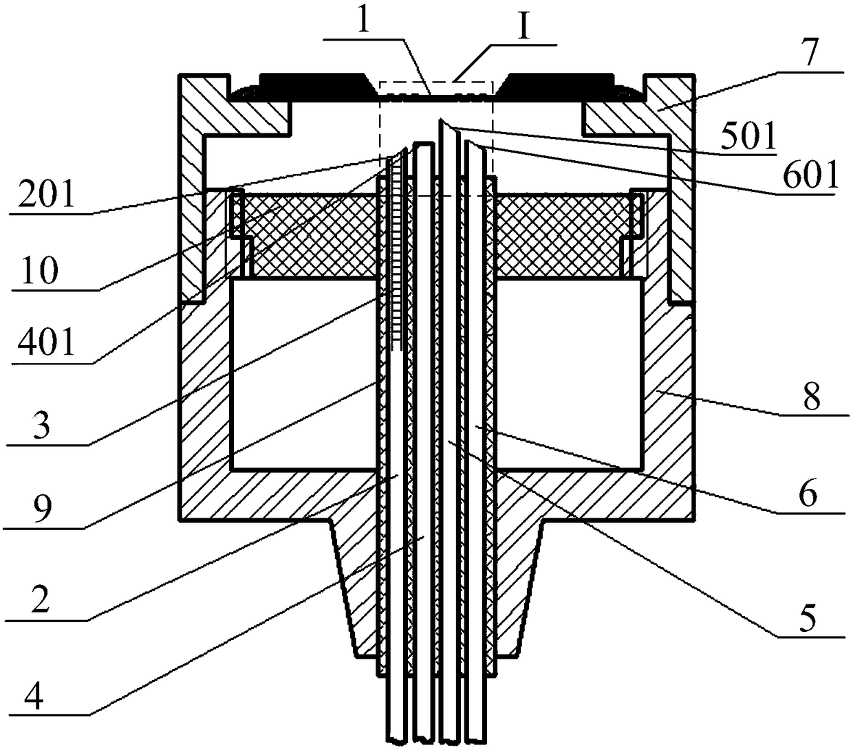
[0034] Embodiment one: combine below figure 1 and figure 2 This embodiment will be described in detail. An optical fiber sensing probe described in this embodiment includes a housing, a pressure sensitive diaphragm 1, a first emitting optical fiber, a second emitting optical fiber, a first receiving optical fiber and a second receiving optical fiber;

[0035] Both ends of the housing are open, and the pressure sensitive diaphragm 1 is arranged on one open end of the housing;

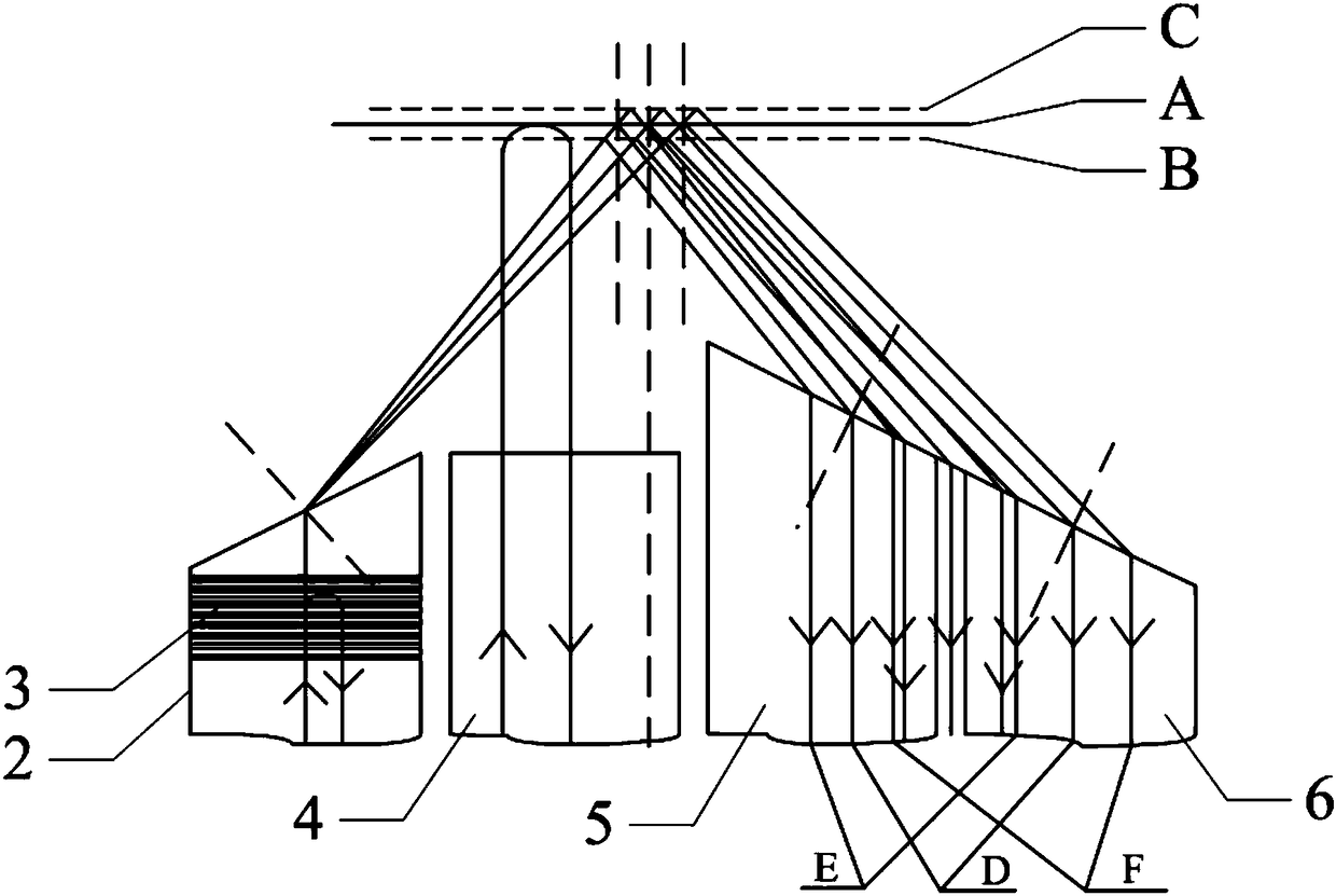
[0036] One end of the first emitting fiber is the first emitting end 2, and the fiber core of the first emitting end is engraved with a fiber grating 3, and the other end of the first emitting fiber is simultaneously connected with the first light source through the first fiber coupler. connected to the first spectrometer;

[0037] One end of the second launch fiber is the second launch end 4, and the other end of the second launch fiber is simultaneously connected to the second light source and the ...

Embodiment 2

[0053] Embodiment two: combine below figure 1 This embodiment will be described in detail. This embodiment is to further limit the optical fiber sensing probe described in the first embodiment.

[0054] An optical fiber sensing probe described in this embodiment, the housing includes an upper housing 7 and a lower housing 8, one open end and the other open end of the housing are respectively located on the upper housing 7 and the lower housing On the body 8, the upper shell 7 is screwed to the lower shell 8.

[0055] In this embodiment, the housing is a split structure, and the upper housing is screwed to the lower housing. The split housing facilitates the assembly of the optical fiber sensing probe and subsequent maintenance and repair.

Embodiment 3

[0056] Embodiment 3: This embodiment further limits the optical fiber sensing probe described in Embodiment 1.

[0057] An optical fiber sensing probe described in this embodiment is provided with a high reflective film on the reflective surface of the pressure sensitive diaphragm 1, the material of the high reflective film is gold, silver, palladium or titanium, and the high reflective film is made of gold, silver, palladium or titanium. The thickness of the reflection film is 10nm to 1000nm.

[0058] In this embodiment, a layer of high reflection film is provided on the reflective surface of the pressure sensitive diaphragm to increase the reflective ability of the pressure sensitive diaphragm.

[0059] In this embodiment, the material of the pressure-sensitive diaphragm is sapphire, silicon or silicon nitride, and the pressure-sensitive diaphragm made of these materials is highly sensitive to external pressure. The pressure-sensitive diaphragm made of sapphire is made by M...


PUM

PropertyMeasurementUnit
thicknessaaaaaaaaaa

Abstract

The invention provides an optical fiber sensing probe, belongs to the technical field of optical fiber sensing, and solves the problems that the present reflective intensity modulated optical fiber sensor has small detectable dynamic range of dynamic signals, small frequency range and low signal-to-noise ratio and the present reflective intensity modulated optical fiber sensor has low accuracy of detection result when it is used for detecting static or quasi-static signals and is liable to be influenced by the change of the light source intensity and the change of the environment temperature. The main content is that optical fiber gratings are engraved on the fiber core of a first transmitting end, a pressure sensitive membrane reflects the optical signals transmitted by the first transmitting end to a first receiving end and a second receiving end, and the optical signals incident to the first receiving end and the optical signals incident to the second receiving end can form differential signals when the pressure sensitive membrane deviates from the initial position. The end surface of a second transmitting end and the reflecting surface of the pressure sensitive membrane form a Fabry-Perot interference cavity. The optical fiber sensing probe is suitable for an optical fiber sensor.

Description

technical field [0001] The invention relates to a sensing probe and belongs to the technical field of optical fiber sensing. Background technique [0002] Reflective intensity modulation fiber optic sensors not only have the common advantages of corrosion resistance, anti-electromagnetic interference and high sensitivity, but also have the characteristics of front-end passive, simple principle, flexible design, reliable performance and low price. Reflective intensity-modulated optical fiber sensors can detect various physical quantities such as strain, displacement, pressure, vibration, temperature and surface roughness, and occupy a very important position in the field of optical fiber sensing technology. [0003] However, the existing reflective intensity-modulated fiber optic sensors still have the following problems: [0004] 1. When the existing reflective intensity modulation optical fiber sensor is used to detect dynamic signals, the dynamic range of the detectable s...

Claims


Application Information

Patent Timeline
Patent Type & Authority Patents(China)
IPC IPC(8): G01D5/26G01L1/24
CPCG01D5/268G01L1/24
Inventor 桂永雷刘兴宇曹永海邵志强张鹏
Owner NO 49 INST CHINESE ELECTRONICS SCI & TECH GRP
Why Eureka
Try Eureka