Active matrix type of display unit and method for driving the same

a display unit and active matrix technology, applied in the direction of static indicating devices, identification means, instruments, etc., can solve the problems of unnecessarily large power consumption, difficult to the user of the display can hardly recognize the displayed contents, so as to prevent the degradation of the display quality of an image caused by slight noise or non-uniform performance of elements, the dynamic range is not narrowed, and the effect of improving the power consumption and the operating life of elements

Inactive Publication Date: 2005-11-17
SONY CORP
View PDF9 Cites 46 Cited by
  • Summary
  • Abstract
  • Description
  • Claims
  • Application Information

AI Technical Summary

Benefits of technology

[0013] The present invention was made in the light of the circumstances as described above, and it is an object of the present invention to provide an active matrix type of display unit enabling easy adjustment of display brightness in response to brightness of the ambient environment without narrowing the dynamic range and a method of driving the display unit.
[0016] In the present invention, a result of detection by the illuminance detector is calculated or processed as a control rate for a light emitting period of time of a light emitting element under control by the control unit independent from the brightness information provided by an image signal supplied from the data drive unit. Control over the light emitting period of time includes adjustment of average brightness of pixels in one scanning cycle. Therefore, by controlling a light emitting period of time of a light emitting element according to illuminance of the ambient environment, namely brightness of external light, it is possible to easily and freely adjust the display brightness without narrowing a dynamic range.
[0017] Control over a light emitting period of time of a light emitting element can easily be carried out by adjusting a percentage (duty) of a light emitting period of time in one light emitting cycle. In other words, the average brightness of pixels in one scanning cycle can easily be adjusted according to a degree of duty.
[0019] Various types of self-luminous elements such as an organic electroluminescence element, an inorganic electroluminescence element, and a light-emitting diode may be used as the light emitting element used in the present invention. Especially, when the present invention is applied to an organic electroluminescence display unit, the power consumption and the operating life of the element can be improved by adjusting the optimal brightness according to the brightness of the environment for use thereof.
[0020] As described above, with the present invention, as the display brightness can be adjusted by controlling a light emitting period of time of a light emitting element, the display brightness can freely be adjusted according to illuminance (brightness) of an environment for use thereof.
[0021] Further the dynamic range is not narrowed, so that degradation of display quality of an image caused by slight noises or non-uniformity in performance of elements can be prevented, and high quality images can always be displayed regardless of the environment for use thereof.

Problems solved by technology

When the organic EL display unit is used as a display for a portable terminal device or a mobile device such as a video camera, peripheral brightness varies according to an environment for use thereof, and sometimes a user of the display can hardly recognize the displayed contents.
When the display brightness is set to a relatively large value, however, the display is too bright at a dark place, which rather makes it difficult to recognize the displayed contents.
Further the power consumption becomes unnecessarily larger, and an operating life of the organic EL display unit is disadvantageously shortened.
However, in the display unit described in Japanese Patent Laid-Open No. 2001-100697, both control over brightness in response to the brightness control signal data and control over the brightness corresponding to the brightness detected by the illuminance detector are performed by the brightness control unit, so image signals and brightness detection signals are intermingled and complicated operations and processing are required to respond to the complicated situation.
Further when used in a dark environment, the brightness is set to a relatively lower value, it is necessary to control the luminance intensity of a light emitting element with a small drive voltage range, so the dynamic range is disadvantageously degraded.
Because of the feature, degradation of image display quality inevitably occurs due to a small noise or non-uniformity in characteristics of elements.

Method used


Image

  • Active matrix type of display unit and method for driving the same
  • Active matrix type of display unit and method for driving the same
  • Active matrix type of display unit and method for driving the same

Examples


Embodiment Construction

[0031] An embodiment of the present invention is described below with reference to the related drawings. In this embodiment, an organic EL active matrix type of display unit using an organic EL element is described as an example of a light emitting element constituting each pixel.

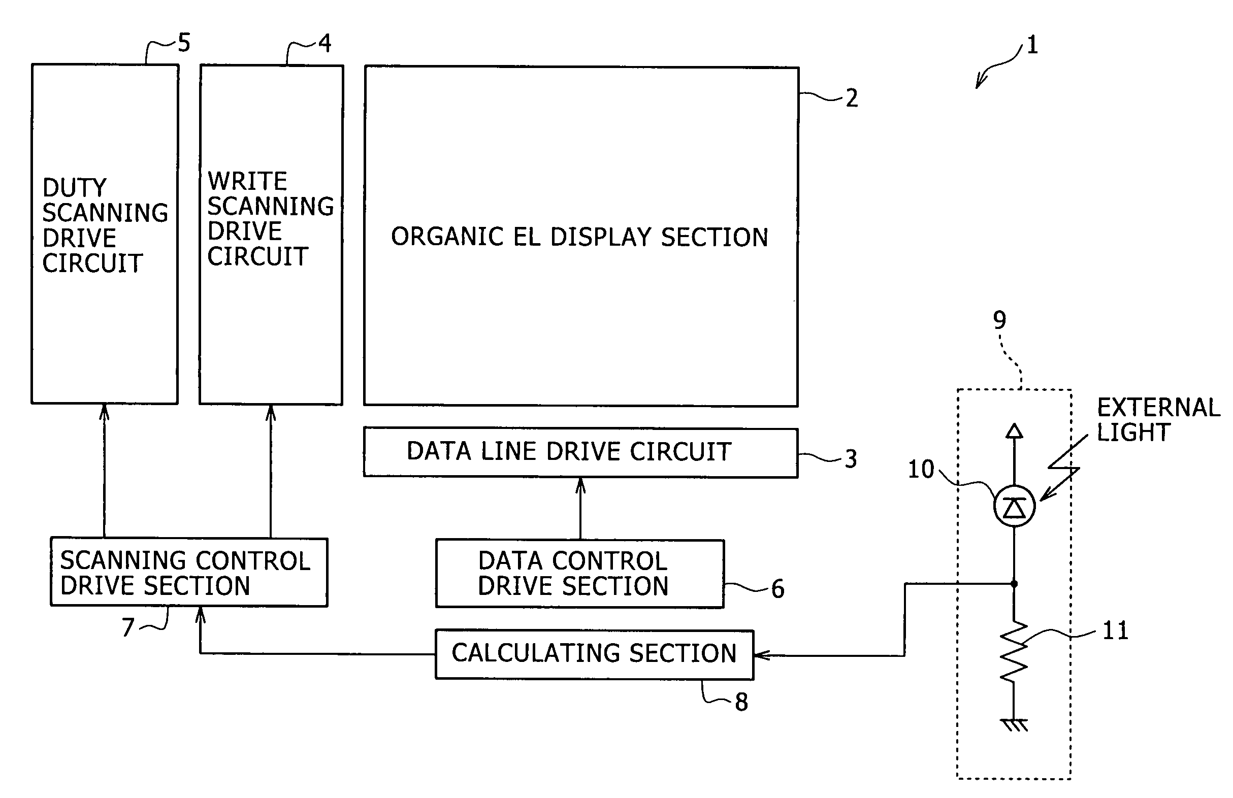
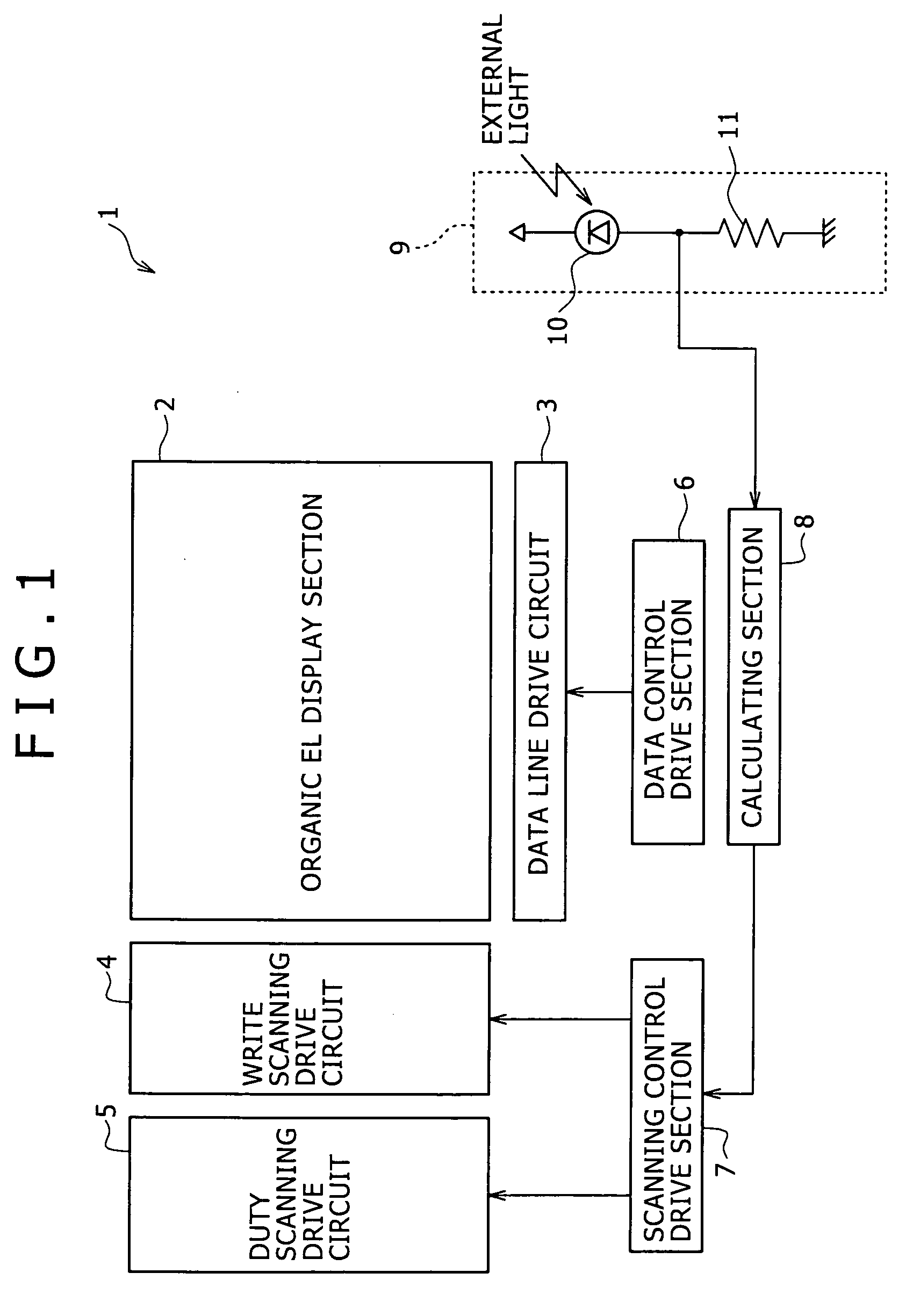
[0032]FIG. 1 is a general block diagram showing an active matrix type of display unit according to an embodiment of the present invention. The organic EL active matrix type of display unit 1 includes an organic EL display section 2, a data line drive circuit 3, a write scanning drive circuit 4, a duty scanning drive circuit 5, a data control drive section 6, a scanning control drive section 7, a calculating section 8, and an illuminance detector 9, and adjusts the display brightness of the organic EL display section 2 in response to illuminance (brightness of external light) of the ambient environment detected by the illuminance detector 9.

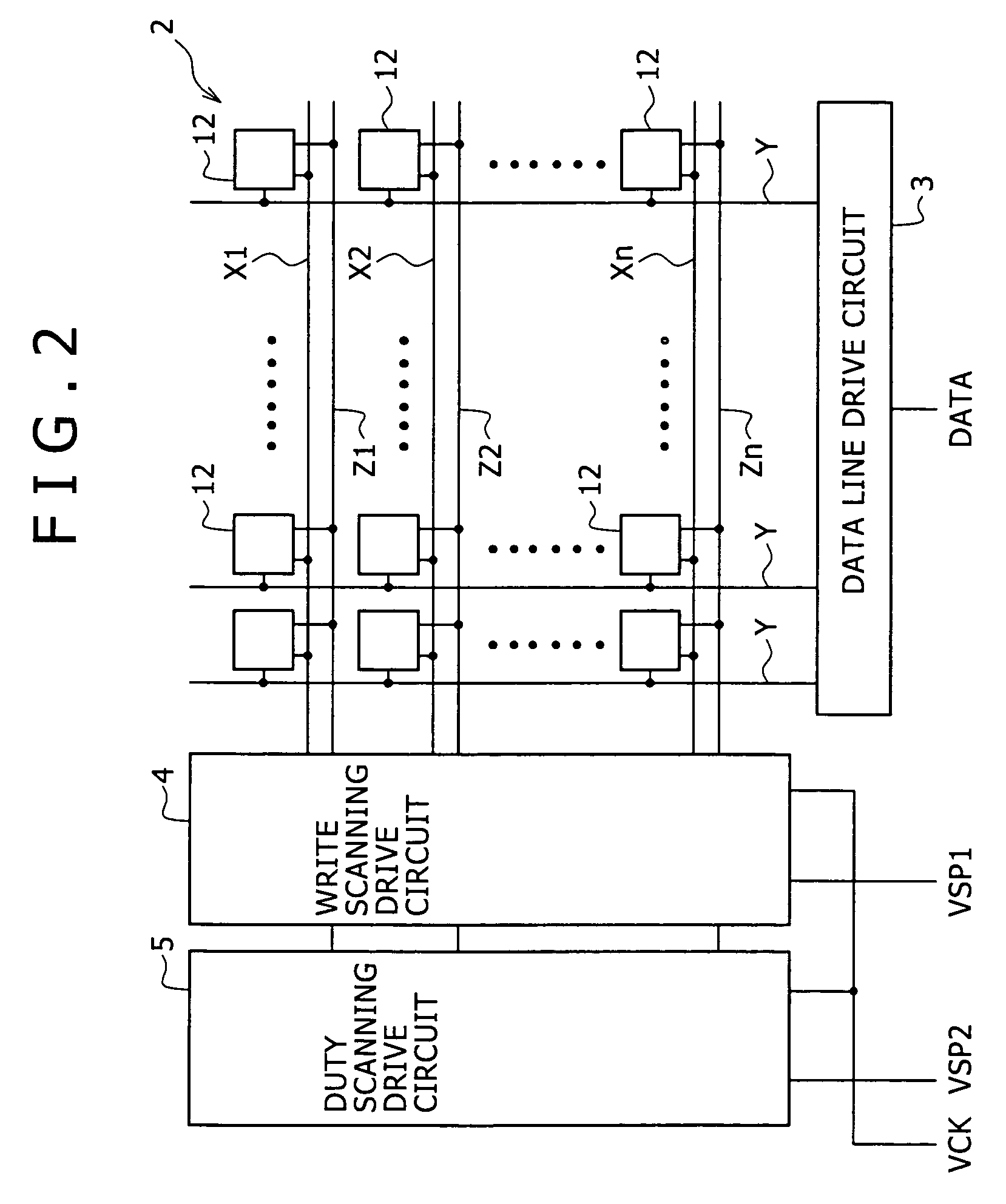
[0033] At first, configuration of the organic EL display section 2...


PUM


Abstract

An organic EL active matrix type of display apparatus includes an illuminance detector for detecting brightness of an ambient environment, a calculating section for calculating a brightness set value corresponding to an output from the illuminance detector, and a duty scanning drive circuit as a control unit for controlling a light emission period of time of an organic EL element according to the brightness set value calculated in this calculating section. The light emission period of time of the organic EL element can be controlled according to a percentage (duty) of a light emission period of time within one scanning cycle. With this duty control, display brightness can easily and smoothly be adjusted. Further the dynamic range is not narrowed, so high image quality can be maintained even at a dark place.

Description

BACKGROUND OF THE INVENTION [0001] The present invention relates to an active matrix type of display unit having an active element for each pixel and providing display control for each pixel with this active element and a method of driving the same, and more specifically an active matrix type of display unit with the display brightness automatically adjustable according to an ambient brightness for upgrading the image quality, saving power, and prolonging the operating life, and a method of driving the same. [0002] Recently there have been made active efforts for development of an organic electroluminescence element display unit using an organic electroluminescent display element (described as organic EL element hereinafter) as one of plane display unit. The organic EL element display device is self-luminous and does not need use of a back light, and in addition is excellent in the performance adapted to moving picture, wide view angle, and color reproducing capability and the like,...

Claims


Application Information

Patent Timeline
Patent Type & Authority Applications(United States)
IPC IPC(8): G09F9/30H01L51/50G09G3/20G09G3/30G09G3/32H01L27/32H05B44/00
CPCG09G3/2014G09G3/3233G09G2320/0626G09G2300/0842G09G2300/0861G09G3/3241G09G3/30G09G3/20
Inventor KAWASE, KIMITAKA
Owner SONY CORP
Why Eureka
Try Eureka