Narrowband filtering signal conditioning method and device of electromagnetic flowmeter

An electromagnetic flowmeter and narrow-band filtering technology, which is applied in the application of electromagnetic flowmeters to detect fluid flow, volume/mass flow generated by electromagnetic effects, etc. It can solve problems such as poor resolution, low signal-to-noise ratio, and difficulty in extending the lower limit of flow measurement. , to achieve the effect of improving the signal-to-noise ratio and improving the performance index

Active Publication Date: 2012-07-04
STATE GRID CORP OF CHINA +1
View PDF0 Cites 0 Cited by
  • Summary
  • Abstract
  • Description
  • Claims
  • Application Information

AI Technical Summary

Problems solved by technology

In the known electromagnetic flowmeter, the amplification of the flow signal generally adopts the peak sample and hold signal conditioning circuit, and its broadband signal amplifying circuit makes a variety of interference noises be amplified together with the flow signal, which inevitably shifts or aliases the noise spectrum to In the frequency band of the flow signal, the signal-to-noise ratio is low, the resolution is poor, and the lower limit of flow measurement is difficult to expand
It can be said that the existing peak sample and hold signal conditioning circuit restricts the development of electromagnetic flowmeter

Method used


Image

  • Narrowband filtering signal conditioning method and device of electromagnetic flowmeter
  • Narrowband filtering signal conditioning method and device of electromagnetic flowmeter
  • Narrowband filtering signal conditioning method and device of electromagnetic flowmeter

Examples


Embodiment 1

[0036] The electromagnetic flowmeter adopts the narrow-band filter signal conditioning method. Firstly, the narrow-band filter signal conditioning is performed, and the sampling is performed when the signal reaches a steady state, which just avoids the interference of the differential noise and suppresses the differential noise. The average excitation current source generates the constant average magnetic field that meets the requirements of the narrowband filter conditioning technology, that is, the constant average current source that realizes closed-loop feedback regulation through sampling and comparison.

[0037] The differential noise suppression is the fundamental wave e1(t) after filtering e(t) high-order harmonics, although the fundamental wave es1(t) of the flow signal and the fundamental wave ec1(t) of the differential noise are included, but the phase The difference is 90o, and the demodulation pulse p(t) is synchronous with es1(t), and the quadrature phase-sensitiv...

Embodiment 2

[0040] Referring to the accompanying drawings, preferred specific embodiments of the present invention will be described in detail.

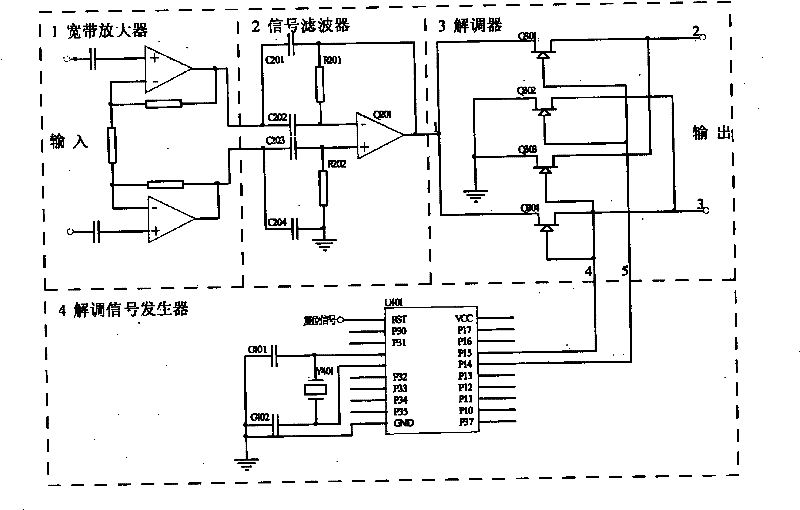
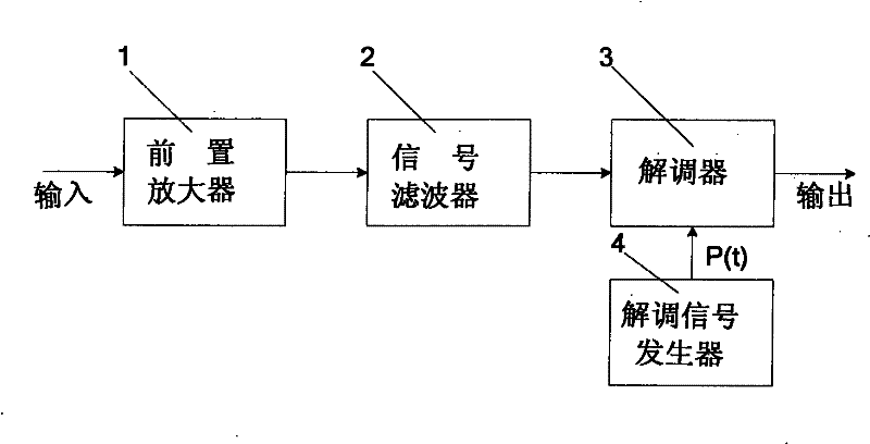
[0041] as attached figure 1 Among them, the narrowband filter signal conditioning circuit includes: a preamplifier 1, a signal filter 2, a demodulator 3 and a demodulation signal generator 4. The preamplifier 1 is connected to the signal filter 2 , the signal filter 2 is connected to the demodulator 3 , and the demodulator 3 is connected to the demodulation signal generator 4 .

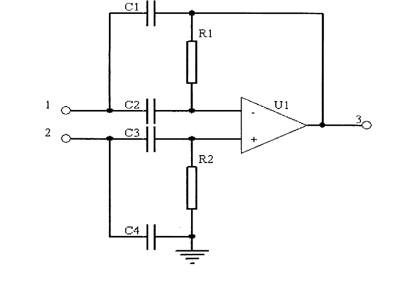
[0042] attached figure 2 The circuit structure of the narrowband filter in the specific scheme of the narrowband filter signal conditioning circuit according to the present invention is given. exist figure 2 , shows the connection relationship of operational amplifier U1, input signal terminals 1 and 2, output signal terminal 3, filter capacitors C1 and C2, C3 and C4, and resistors R1 and R2.

[0043]In this circuit structure, the inverting input terminal of the o...

Embodiment 3

[0052] The invention proposes a narrow-band filtering signal conditioning technology and a constant-average current excitation technology, so that the signal-to-noise ratio of the micro-flow signal can be improved.

[0053] 1 Introduction to the working principle of the narrowband filter electromagnetic flowmeter of the present invention

[0054] According to the principle of Faraday's electromagnetic induction, when the conductive fluid in the measuring pipeline moves at the flow velocity v(t) to cut the magnetic induction line, the induced electromotive force (flow signal) e(t) will be obtained between the detection electrodes. Figure 8 It is a schematic block diagram of a narrow-band filter micro-flow electromagnetic flowmeter. The coil of the sensor driven by the excitation power supply generates an alternating magnetic field B(t). If B(t) is used as the carrier signal and the flow velocity v(t) is used as the modulation signal, the induced electromotive force e( t)=D B(t...


PUM


Abstract

The invention relates to narrowband filtering signal conditioning method and device of an electromagnetic flowmeter. In the prior art, a peak sampling and holding signal conditioning circuit is commonly adopted to amplify a flow signal, the interference noise is amplified together with the flow signal through a broadband signal amplification circuit, and a noise frequency spectrum is shifted or aliased into a frequency band of the flow signal, therefore, the problems of low signal-to-noise ratio, poor resolution ratio and difficult expansion of lower flow measurement limit are caused. In the invention, narrowband filtering signal conditioning is firstly carried out; when a signal reaches a stable state, the sampling is carried out, which just avoids the interference from differential noise, therefore, the differential noise is restricted; and a constant mean magnetizing current source which has constant current mean in each cycle generates a constant mean magnetic field required by a narrowband filter conditioning technology, that is to say, the closed loop feedback conditioning to the constant mean current source is realized by sampling and comparing. The invention is used for filtering the superposed interference noise of the flow signal and improves the performance of the electromagnetic flowmeter, thereby expanding the lower flow measurement limit and realizing the accurate micro-flow measurement.

Description

Technical field: [0001] The invention relates to a narrow-band filtering signal conditioning circuit, more precisely, relates to a signal conditioning technology for a micro-flow electromagnetic flowmeter. Background technique: [0002] In the field of flow measurement, with the development of modern industry, especially medical and health, bioengineering and fine chemical industries have put forward newer and higher requirements for the performance indicators of flowmeters. In the known electromagnetic flowmeter, the amplification of the flow signal generally adopts the peak sample and hold signal conditioning circuit, and its broadband signal amplifying circuit makes a variety of interference noises be amplified together with the flow signal, which inevitably shifts or aliases the noise spectrum to In the frequency band of the flow signal, the signal-to-noise ratio is low, the resolution is poor, and the lower limit of flow measurement is difficult to expand. It can be sa...

Claims


Application Information

Patent Timeline
Patent Type & Authority Patents(China)
IPC IPC(8): G01F1/58
Inventor 牛滨周真于晓洋孙晶华马德仲吴海滨
Owner STATE GRID CORP OF CHINA
Why Eureka
Try Eureka