
Residual heat recovery system and operation method thereof
A waste heat recovery system and electronically controlled valve technology, which can be applied to heating devices and other non-combustion heat generation directions, can solve the problems of waste and difficulty in recycling, and achieve the effect of large waste heat recovery efficiency.
- Summary
- Abstract
- Description
- Claims
- Application Information
AI Technical Summary
Problems solved by technology
Method used
Image

Examples
Embodiment Construction
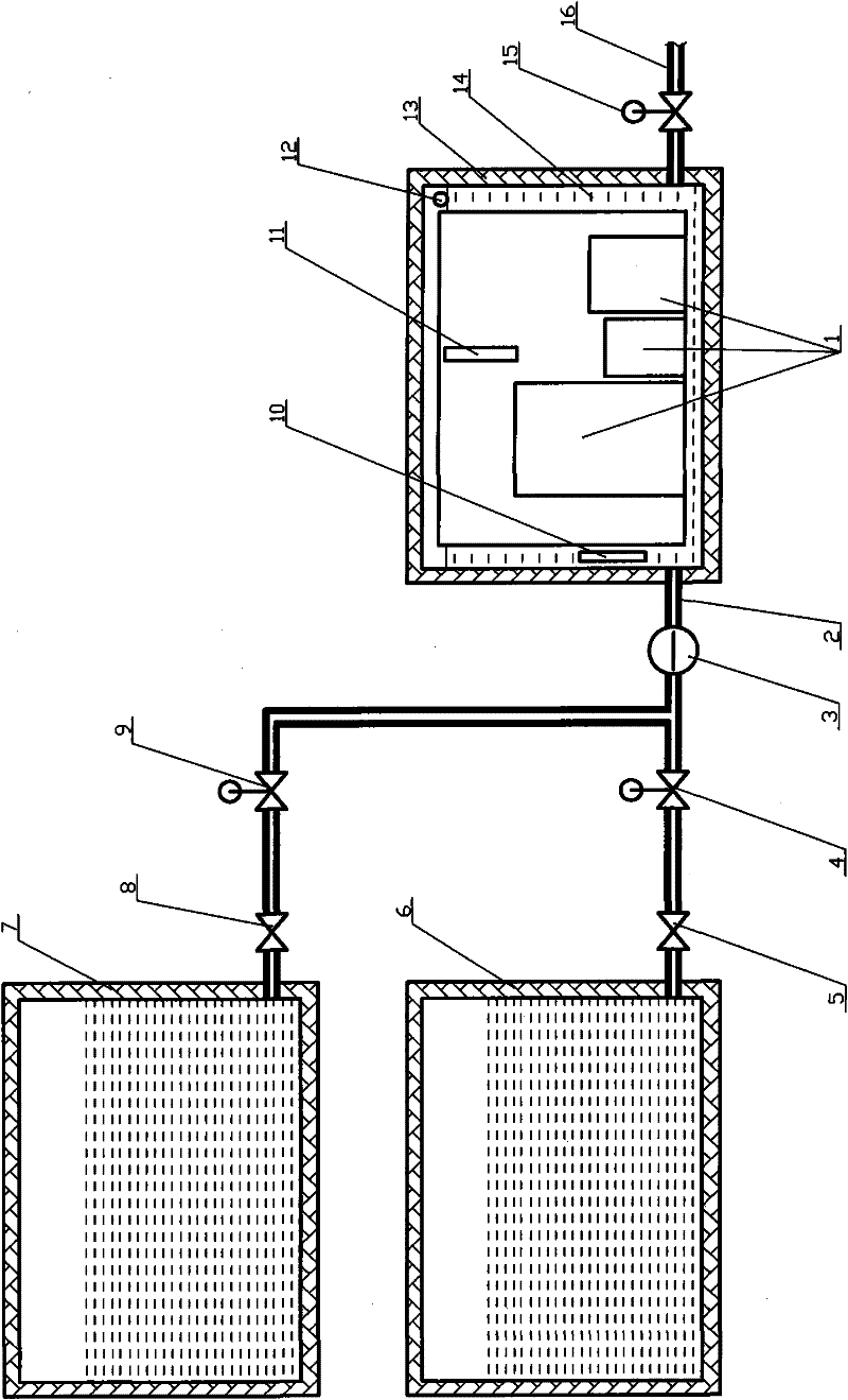
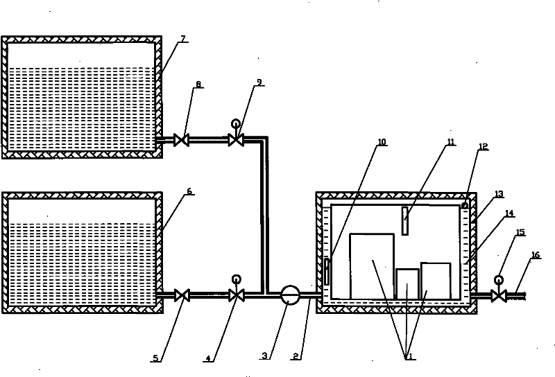
[0016] The present invention will be further described below in conjunction with the accompanying drawings. Such as figure 1 As shown, a waste heat recovery system includes an electronically controlled water pump 3, a boiling water incubator 6, a warm water incubator 7, a temperature sensor A10, a temperature sensor B11, a liquid level sensor 12, an incubator 13 and a cooling water tank 14. The heat preservation Cooling water tank 14 is installed in the case 13, and left and right sides respectively have a pipeline interface, and the interface on the left is connected with boiling water incubator 6 by pipeline A2, electric control water pump 3, electric control valve A4, one-way valve A5, and At the same time, the pipeline A2, the electric control water pump 3, the electric control valve B9, the one-way valve B8 are connected with the warm water incubator 7, and the interface on the right is connected to the pipeline B16, and the pipeline B16 is equipped with an electric contr...
PUM
 Abstract
Description
Claims
Application Information