Speed reducer

A reducer, gear shaft technology, applied in the direction of gear transmission, belt/chain/gear, mechanical equipment, etc., can solve the problems of low efficiency, high manufacturing cost and high cost of worm gear reducer and bevel gear reducer. Non-linear coupling problems, long service life, and the effect of strong bearing capacity

Inactive Publication Date: 2011-05-18
CHONGQING AEROSPACE POLYTECHNIC COLLEGE
View PDF3 Cites 6 Cited by
  • Summary
  • Abstract
  • Description
  • Claims
  • Application Information

AI Technical Summary

Problems solved by technology

[0003] In the prior art, although cylindrical gear reducers, worm gear reducers, bevel gear reducers, harmonic reducers and cycloid planetary reducers are widely used in transmission systems in engineering fields such as rail vehicles, engineering machinery, robots and aerospace application, but the cylindrical gear reducer has a large volume, heavy structure and small transmission ratio; the worm gear reducer and bevel gear reducer have low efficiency, high manufacturing cost and harsh assembly conditions; the harmonic reducer flex wheel has low torsional stiffness, small torque and Low reliability; cycloid planetary reducer is bulky and costly
Moreover, none of the above-mentioned types of reducers can solve the problems of the transmission mechanism and system unsteady fluctuations caused by the large manufacturing and assembly errors of the reducer and the low level of static and dynamic balance during the transmission process of the engineering vehicle reducer.
Especially for engineering vehicles under harsh working conditions and extreme environments, the unsteady wear, vibration and noise of the reducer transmission mechanism and system will increase, which will lead to serious problems such as gear jamming and component failure.

Method used


Image

  • Speed reducer
  • Speed reducer

Examples


Embodiment Construction

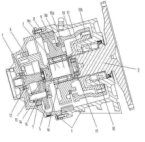
[0022] The accompanying drawing is a schematic diagram of the general assembly structure of the reducer.

[0023] As shown in the figure, the speed reducer of the present invention includes a power input gear shaft 1, a first-stage planetary gear transmission assembly, an eccentric shaft 2 whose axis deviates parallel to the axis of the power input gear shaft, a two-stage double planetary gear transmission assembly, and a power output gear Shaft 3 and reducer housing 4;

[0024] The first-stage planetary gear transmission assembly includes: a first-stage planetary gear 5, a planet carrier 6, and a first-stage sun gear 7; the first-stage planetary gear 5 meshes with the power input gear shaft 1, and the first-stage sun gear 7 is fixedly arranged In the reducer housing 4, the planet carrier 6 is in transmission cooperation with the eccentric shaft 2;

[0025] The two-stage double planetary gear transmission assembly includes: a two-stage double planetary gear 8, a two-stage sun...


PUM


Abstract

The invention discloses a speed reducer, which comprises a power input gear shaft, a first-level planet gear transmission component, an eccentric shaft of which the axis is deflected to the axis of the power input gear shaft in parallel, a second-level planet gear transmission component, a power output gear shaft and a speed reducer shell. The speed reducer employs the planet gear transmission mechanism, so the structure is compact; the floating planet gear transmission mechanism can adaptively compensate manufacturing and assembling errors and abnormal abrasion, and has small transmission error and high precision. In the transmission process, the differential transmission way of the rare-tooth planet gear of the speed reducer increases the number of meshed teeth in a transmission process, ensures strong bearing capability, stable transmission, low transmission noise and high transmission efficiency, and solves the nonlinear coupling problem of the speed reducer under an extreme working condition. In the transmission process, cambered drum teeth of the speed reducer can filter fluctuations caused by processing and installation errors and the bad working condition, so the abrasion is lowered, the transmission is more stable, the noise is lower, and the service life is longer.

Description

technical field [0001] The invention relates to a transmission device, in particular to a reduction transmission device. Background technique [0002] With the rapid development of construction industries such as real estate, railways, highways, bridges and tunnels, construction machinery equipment has developed rapidly in the engineering field. High performance requirements such as low power consumption, high reliability, high precision, long life, high power and maintenance-free. [0003] In the prior art, although cylindrical gear reducers, worm gear reducers, bevel gear reducers, harmonic reducers and cycloid planetary reducers are widely used in transmission systems in engineering fields such as rail vehicles, engineering machinery, robots and aerospace application, but the cylindrical gear reducer has a large volume, heavy structure and small transmission ratio; the worm gear reducer and bevel gear reducer have low efficiency, high manufacturing cost and harsh assembl...

Claims


Application Information

Patent Timeline
Patent Type & Authority Applications(China)
IPC IPC(8): F16H1/32
Inventor 罗绍华何履胜温智灵
Owner CHONGQING AEROSPACE POLYTECHNIC COLLEGE
Why Eureka
Try Eureka