New bunker device

A new type of silo technology, used in packaging, large containers, transportation and packaging, etc., can solve problems such as increasing labor intensity and achieve the effect of good connection status

Inactive Publication Date: 2011-05-25
WUXI HUAZHONG TECH
View PDF6 Cites 1 Cited by
  • Summary
  • Abstract
  • Description
  • Claims
  • Application Information

AI Technical Summary

Problems solved by technology

The channel steel on the base and the channel steel on the silo are in contact with each other through the side, because the side of the channel steel is generally narrow, in order to achieve the installation accuracy, it is necessary to drill more bolts when connecting the base and the silo hole, increased labor intensity

Method used


Image

  • New bunker device
  • New bunker device
  • New bunker device

Examples


Embodiment 1

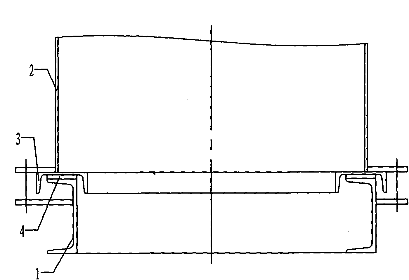
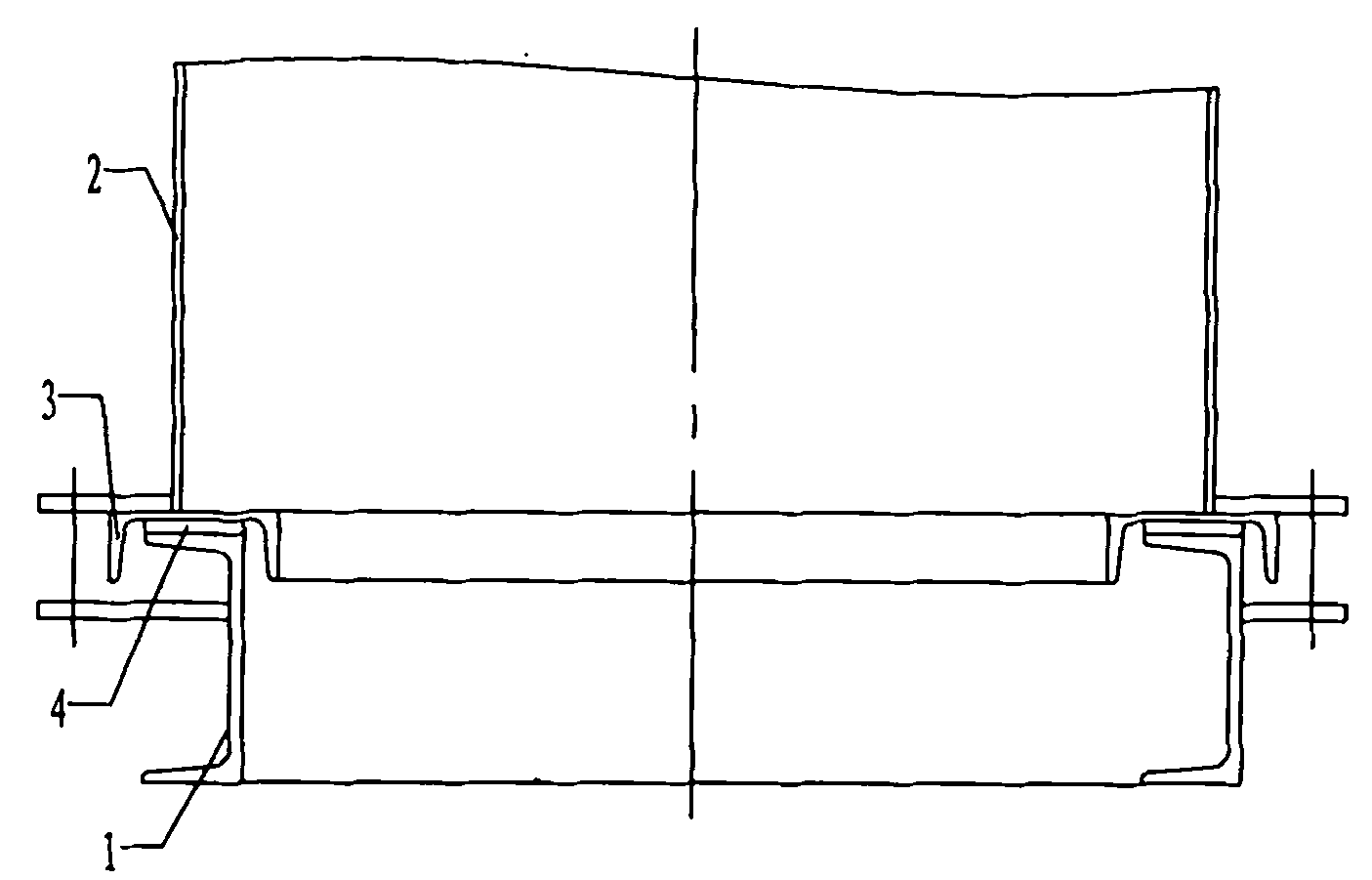
[0014] Such as figure 2 As shown, the embodiment of the silo device of the present invention includes a base 1, which is a cavity with an upper opening and a lower opening, and the base 1 is welded end to end by channel steel in sequence. The upper opening of the base 1 is fixedly connected with a silo 2 communicating with the cavity, and a week of channel steel 3 is welded at the bottom of the silo. 1 on the upper opening. A gasket 4 is pressed between the bottom of the draw-in groove and the upper opening of the base, and the feed bin presses down the gasket by gravity, so that the gasket 4 has the function of shock absorption and can well prevent dust from spilling out. In addition, horizontal connecting plates are respectively directly welded on the base and the silo, and the upper and lower opposite connecting plates are connected by bolts, which are not shown in the figure.


PUM


Abstract

The invention relates to a new bunker device which comprises a base, and the base is a cavity which has an upper opening and a lower opening; and the upper opening of the base is fixedly connected with a bunker communicated with the cavity, the bottom of the bunker is provided with a clamping groove with an downward opening, and the clamping groove is buckled on the upper opening of the base. The bunker device provided by the invention has the advantages that the bottom of the bunker is provided with the clamping groove clamped with the upper opening of the base, and the clamping groove after being clamped with the upper opening has the function of positioning, therefore, the occurrence of horizontal movement between the bunker and the base can be prevented, so that a good connection status can be realized by using less bolts.

Description

technical field [0001] The invention relates to a novel material bin device, which belongs to the technical field of material conveying equipment. Background technique [0002] The silo device is the most commonly used equipment in the transmission of powdery materials. At present, there is such a silo device, such as figure 1 As shown, a base 5 is included, and the base 5 is a cavity with an upper opening and a lower opening, and the cavity is welded end to end by channel steel. A feed bin 6 is installed by bolts above the base, and the feed bin 6 is made up of a conical hopper and channel steel welded below the conical hopper. The channel steel on the base and the channel steel on the silo are in contact with each other through the side, because the side of the channel steel is generally narrow, in order to achieve the installation accuracy, it is necessary to drill more bolts when connecting the base and the silo holes, increasing the labor intensity. Contents of the...

Claims


Application Information

Patent Timeline
Patent Type & Authority Applications(China)
IPC IPC(8): B65D90/12B65D90/00
Inventor 吴晓亮唐季锋
Owner WUXI HUAZHONG TECH
Why Eureka
Try Eureka