Uplink synchronous control method, system and base station

A synchronization control and base station technology, which is applied in the direction of synchronization devices, baseband system components, and communication between multiple stations, and can solve problems such as interference, affecting reception quality, and different values

Inactive Publication Date: 2015-01-28
ZTE CORP
View PDF3 Cites 0 Cited by
  • Summary
  • Abstract
  • Description
  • Claims
  • Application Information

AI Technical Summary

Problems solved by technology

And when there are multiple types of uplink channels for the same user in the same time slot, multiple timing advances will be generated, and these multiple timing advances may have different values, so that the bursts sent on different code channels corresponding to different uplink channels will be It will be misaligned in time, which will reduce the orthogonality between code channels, interfere with each other, and affect the quality of reception

Method used


Image

  • Uplink synchronous control method, system and base station
  • Uplink synchronous control method, system and base station
  • Uplink synchronous control method, system and base station

Examples


Embodiment 1

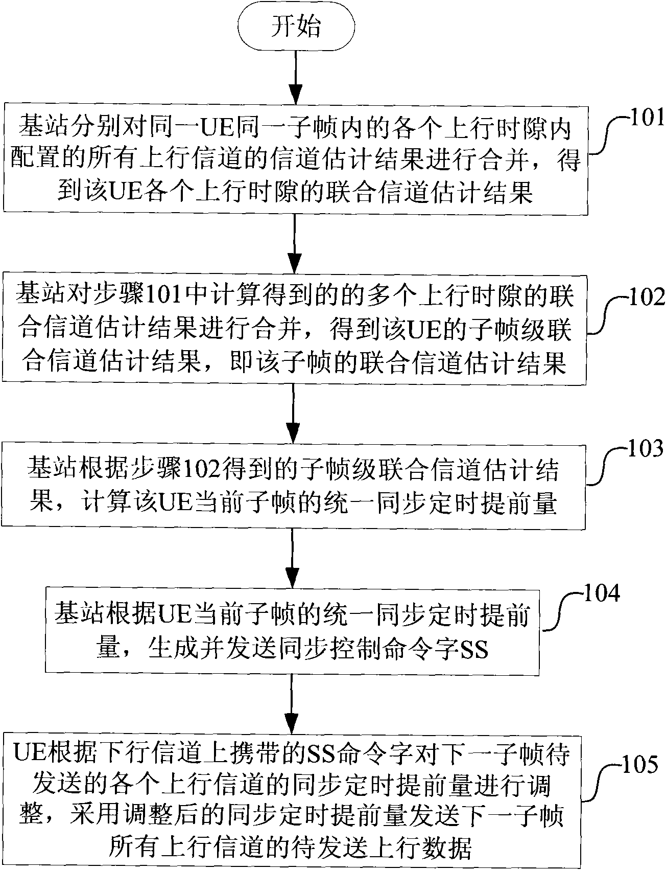
[0102] Embodiment 1: subframe-level synchronization control, such as figure 1 shown, including:

[0103] Step 101, the base station combines channel estimation results of all uplink channels configured in each uplink time slot in the same subframe of the same user equipment (UE), respectively, to obtain joint channel estimation results for each uplink time slot of the UE;

[0104] The joint channel estimation of each uplink time slot can be calculated according to the following formula:

[0105] h pow , j ts = | Σ mid = 0 MidNum - 1 h mid , j ...

Embodiment 2

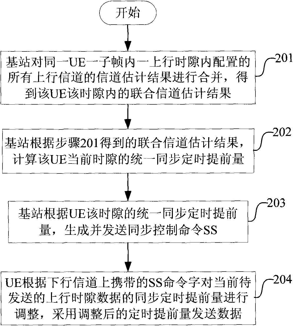
[0139] Embodiment 2: time slot level synchronization control, such as figure 2 shown.

[0140] This embodiment is mainly aimed at the following situation: there is no situation that the same type of uplink channel of the same user is located in multiple uplink time slots in the same subframe, that is, the same type of uplink channel is located in one uplink time slot.

[0141] Step 201, the base station combines the channel estimation results of all uplink channels configured in one uplink time slot in one subframe of the same UE, to obtain the joint channel estimation result of the UE in this time slot;

[0142] The joint channel estimation can be calculated according to formula (1) or formula (2).

[0143] Step 202, the base station calculates the unified synchronization timing advance of the current time slot of the UE according to the joint channel estimation result obtained in step 201;

[0144] When calculating the unified synchronization timing advance of the UE, the...

Embodiment 3

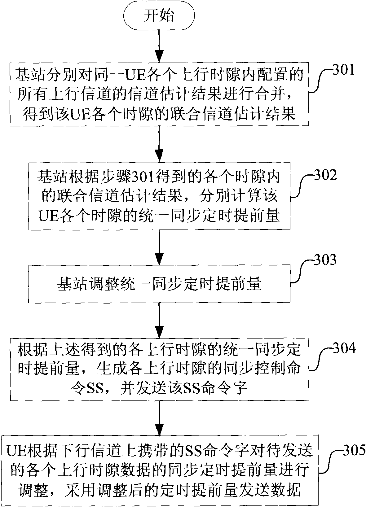
[0164] Embodiment 3: time slot level synchronization control, such as image 3 shown.

[0165] This embodiment mainly addresses the following situation: the same type of uplink channel of the same user is located in multiple uplink time slots in the same subframe, that is, the same type of uplink channel is located in multiple uplink time slots.

[0166] Step 301, the base station combines channel estimation results of all uplink channels configured in each uplink time slot of the same UE respectively, to obtain a joint channel estimation result of each time slot of the UE;

[0167] The joint channel estimation can be calculated according to formula (1) or formula (2).

[0168] Step 302, the base station calculates the unified synchronization timing advance of each time slot of the UE according to the joint channel estimation results in each time slot obtained in step 301;

[0169] Step 303, the base station adjusts the unified synchronization timing advance; the base statio...


PUM


Abstract

The invention discloses an uplink synchronous control method, a system and a base station for avoiding interference and improving receiving quality. The uplink synchronous control method comprises that: the base station only measures and calculates a synchronous timing advance for one time for the same user equipment (UE) in a unit time, generates synchronous control (SS) command words according to the measured and calculated synchronous timing advance, and sends the SS command words to the UE; and the UE regulates the synchronous timing advance of uplink data to be transmitted in a transmitting period under all uplink channels in the unit time according to the indications of the SS command words, and transmits the uplink data by adopting the regulated synchronous timing advance.

Description

technical field [0001] The invention relates to a Time Division Synchronous Code Division Multiple Access (TD-SCDMA) system, in particular to an uplink synchronization control method, system and base station in the TD-SCDMA system. Background technique [0002] In order to realize the synchronization of each uplink channel, the base station needs to continuously detect the arrival time of the midamble in the uplink time slot, and obtain the timing advance of the data sent by the UE, so as to maintain synchronization. Wherein, the base station obtains the timing time difference between the base station and the UE according to the channel estimation result, and calculates the timing advance of the data sent by the UE according to the time difference. In addition, since the UE is usually in a moving state, the base station also needs to adjust the timing advance of the data sent by the UE according to the situation of the UE, so as to realize uplink synchronization control. ...

Claims


Application Information

Patent Timeline
Patent Type & Authority Patents(China)
IPC IPC(8): H04W56/00H04B7/26H04L25/02
Inventor 林伟马毅华耿鹏
Owner ZTE CORP
Why Eureka
Try Eureka