Uplink synchronous control method, system and base station
A synchronization control and base station technology, which is applied in the direction of synchronization devices, baseband system components, and communication between multiple stations, and can solve problems such as interference, affecting reception quality, and different values
- Summary
- Abstract
- Description
- Claims
- Application Information
AI Technical Summary
Problems solved by technology
Method used
Image
Examples
Embodiment 1
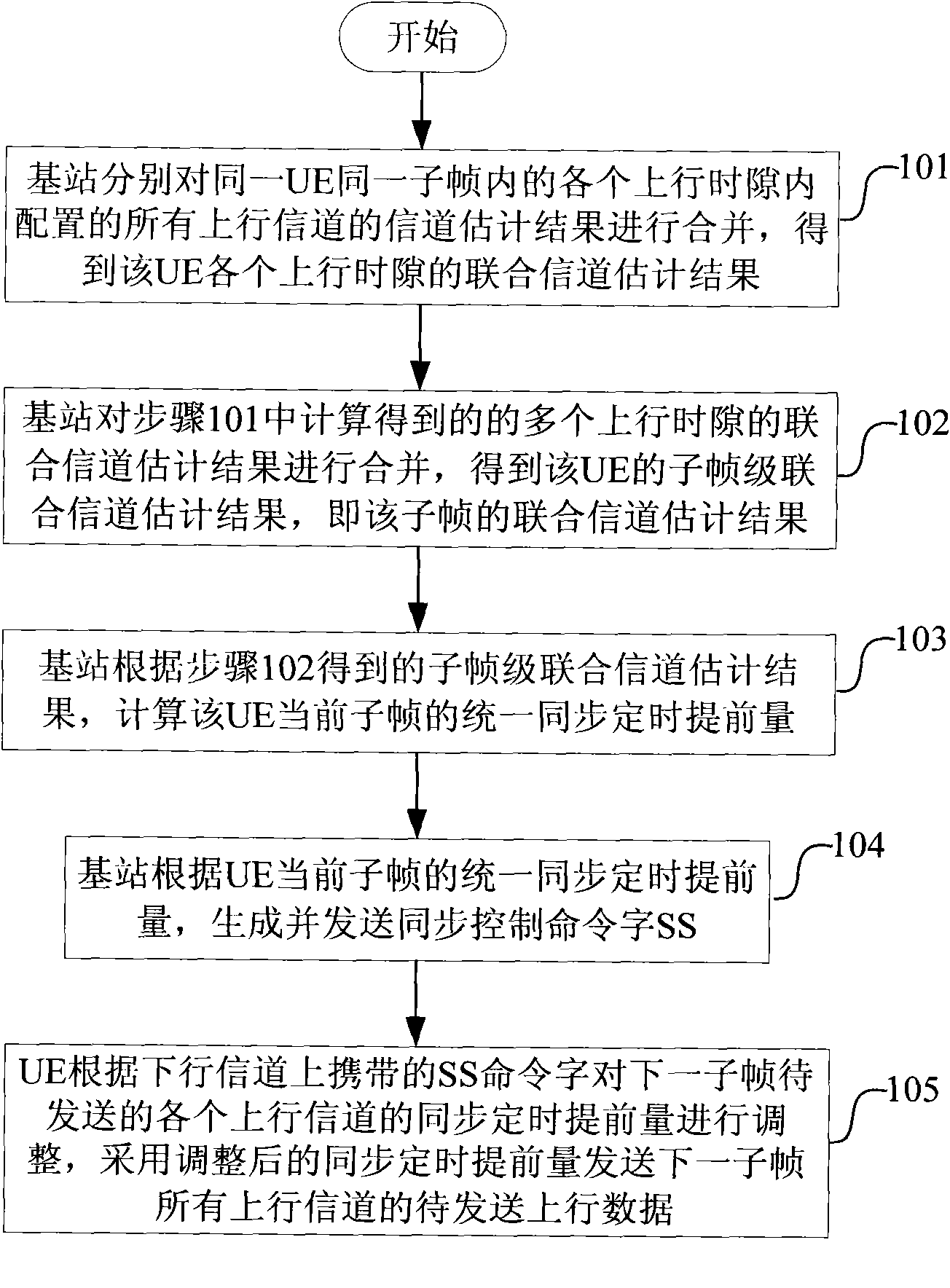
[0102] Embodiment 1: subframe-level synchronization control, such as figure 1 shown, including:
[0103] Step 101, the base station combines channel estimation results of all uplink channels configured in each uplink time slot in the same subframe of the same user equipment (UE), respectively, to obtain joint channel estimation results for each uplink time slot of the UE;
[0104] The joint channel estimation of each uplink time slot can be calculated according to the following formula:
[0105] h pow , j ts = | Σ mid = 0 MidNum - 1 h mid , j | 2 ...
Embodiment 2
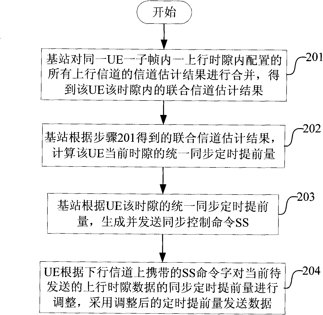
[0139] Embodiment 2: time slot level synchronization control, such as figure 2 shown.
[0140] This embodiment is mainly aimed at the following situation: there is no situation that the same type of uplink channel of the same user is located in multiple uplink time slots in the same subframe, that is, the same type of uplink channel is located in one uplink time slot.
[0141] Step 201, the base station combines the channel estimation results of all uplink channels configured in one uplink time slot in one subframe of the same UE, to obtain the joint channel estimation result of the UE in this time slot;
[0142] The joint channel estimation can be calculated according to formula (1) or formula (2).
[0143] Step 202, the base station calculates the unified synchronization timing advance of the current time slot of the UE according to the joint channel estimation result obtained in step 201;
[0144] When calculating the unified synchronization timing advance of the UE, the...
Embodiment 3
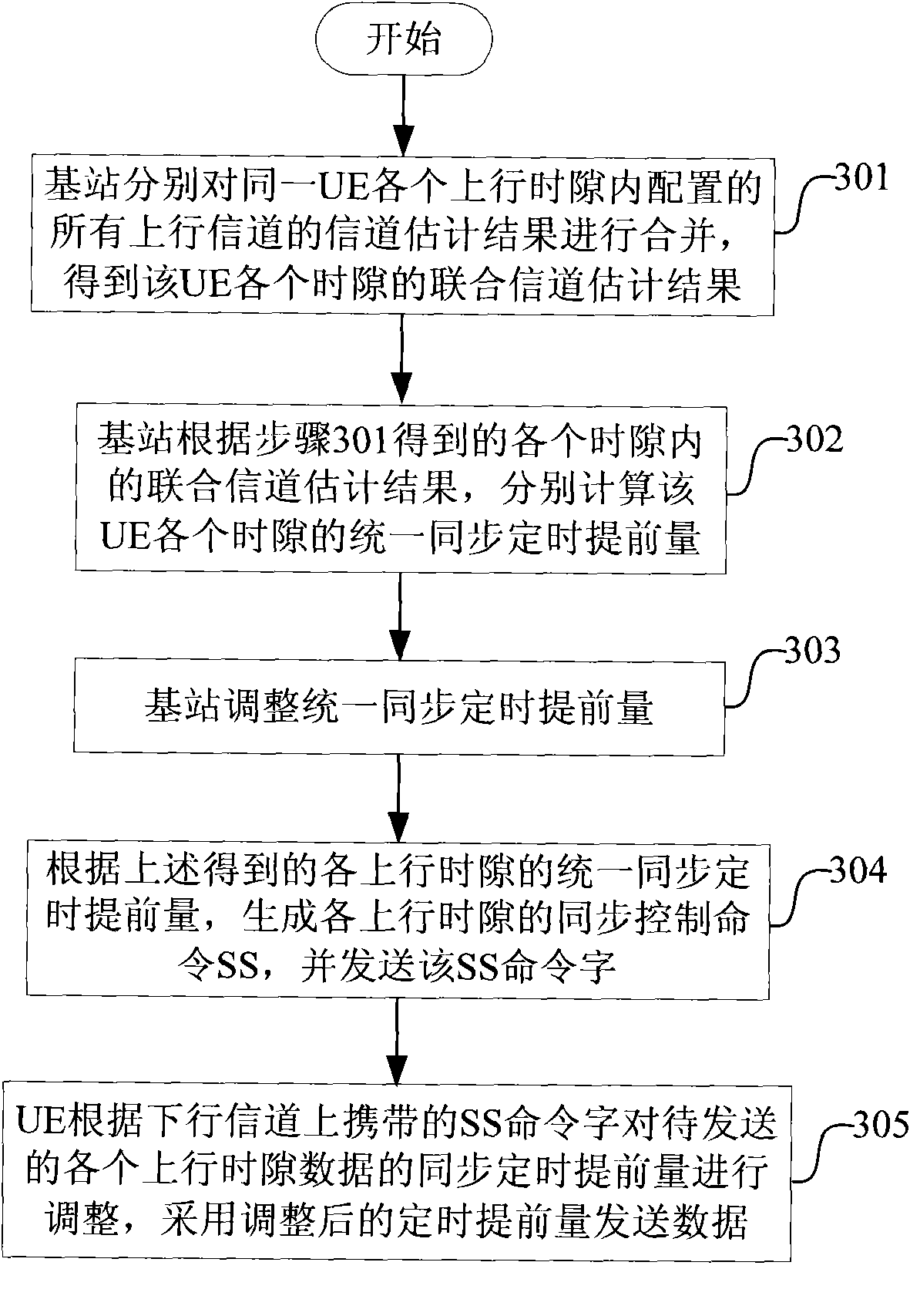
[0164] Embodiment 3: time slot level synchronization control, such as image 3 shown.
[0165] This embodiment mainly addresses the following situation: the same type of uplink channel of the same user is located in multiple uplink time slots in the same subframe, that is, the same type of uplink channel is located in multiple uplink time slots.
[0166] Step 301, the base station combines channel estimation results of all uplink channels configured in each uplink time slot of the same UE respectively, to obtain a joint channel estimation result of each time slot of the UE;
[0167] The joint channel estimation can be calculated according to formula (1) or formula (2).
[0168] Step 302, the base station calculates the unified synchronization timing advance of each time slot of the UE according to the joint channel estimation results in each time slot obtained in step 301;
[0169] Step 303, the base station adjusts the unified synchronization timing advance; the base statio...
PUM
 Abstract
Description
Claims
Application Information
 - R&D
- Intellectual Property
- Life Sciences
- Materials
- Tech Scout
- Unparalleled Data Quality
- Higher Quality Content
- 60% Fewer Hallucinations
Browse by: Latest US Patents, China's latest patents, Technical Efficacy Thesaurus, Application Domain, Technology Topic, Popular Technical Reports.
© 2025 PatSnap. All rights reserved.Legal|Privacy policy|Modern Slavery Act Transparency Statement|Sitemap|About US| Contact US: help@patsnap.com


