
Device for detecting cam profile
A technology for detecting device and cam profile, which is applied to measuring devices, optical devices, instruments, etc., can solve the problem of not being able to adapt to the production of automatic cam lines, and achieve the effects of good system dynamic performance, wide range of motion speed and high measurement accuracy.
- Summary
- Abstract
- Description
- Claims
- Application Information
AI Technical Summary
Problems solved by technology
Method used
Image


Examples
Embodiment Construction
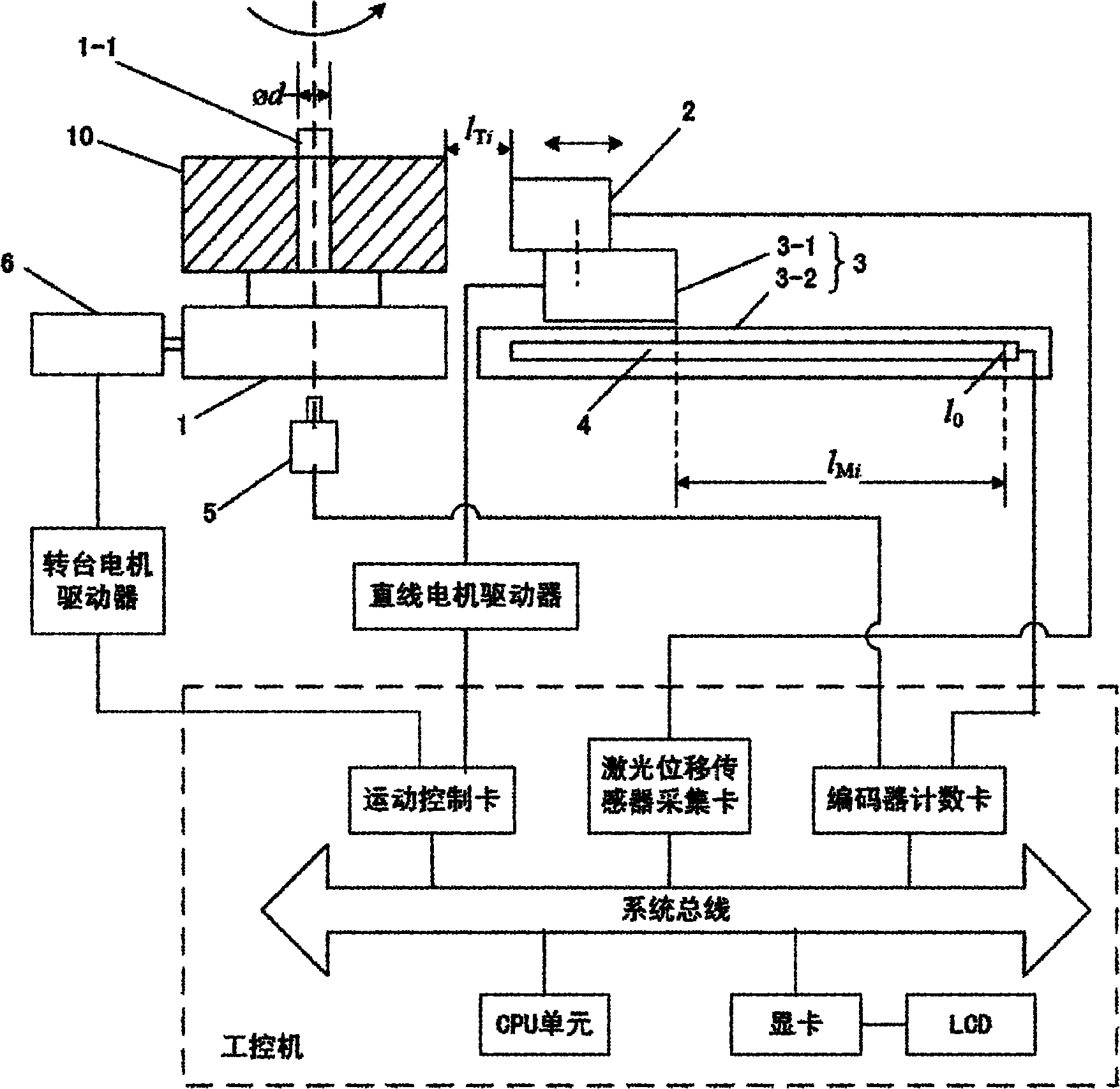
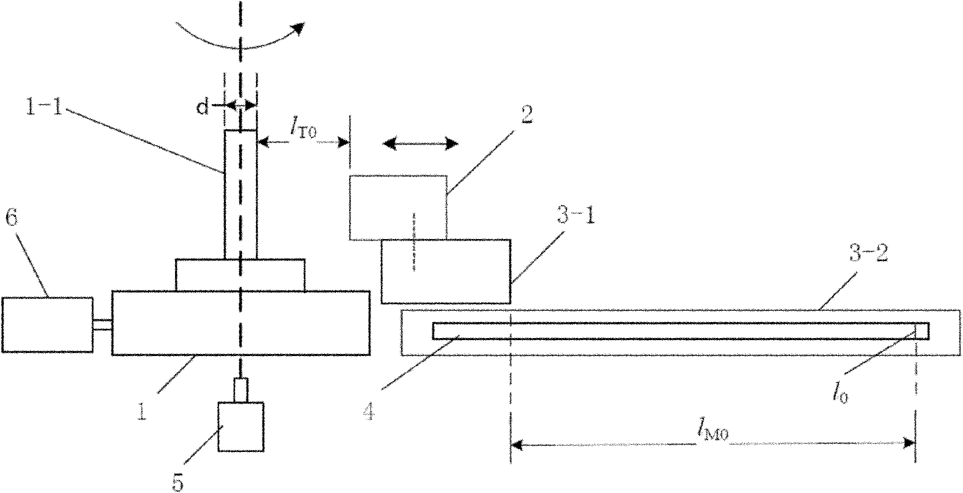
[0021] See Figure 1-2 , the cam profile detection device of the present embodiment includes: a numerically controlled turntable 1 for driving the cam 10 to rotate horizontally coaxially around a vertical mandrel 1-1, a linear motor 3 horizontally arranged on one side of the numerically controlled turntable 1, and a linear motor 3 arranged on the On the mover 3-1 of the linear motor 3 and the laser measuring head 2 on one side of the cam 10, the grating scale displacement sensor 4 for measuring the horizontal displacement of the mover 3-1, for detecting the rotation of the cam 10 Encoder 5 of angle, and industrial computer; The industrial computer controls the action of the numerically controlled turntable 1 and the linear motor 3, and obtains according to the data measured by the laser measuring head 2, the grating ruler displacement sensor 4 and the encoder 5 Outline data of the cam 10.
[0022] As an optimal implementation, the centerline of the stator 3-2 of the linear mo...
PUM
 Abstract
Description
Claims
Application Information