Device for detecting cam profile

A detection device and cam profile technology, applied in the direction of measuring devices, optical devices, instruments, etc., can solve the problems of not being able to adapt to the production of cam automatic lines, and achieve the effect of good dynamic performance, fast speed and high precision of the system

Inactive Publication Date: 2012-06-20
CHANGZHOU INST OF TECH
View PDF0 Cites 14 Cited by
  • Summary
  • Abstract
  • Description
  • Claims
  • Application Information

AI Technical Summary

Problems solved by technology

To achieve high-precision and high-efficiency detection of cams, correct processing and evaluation of its errors, and timely and rapid feedback of cam quality information, traditional optical-mechanical measuring instruments and manual data processing methods can no longer adapt to the wide range of cams. The need for automatic line production

Method used


Image

  • Device for detecting cam profile
  • Device for detecting cam profile
  • Device for detecting cam profile

Examples


Embodiment Construction

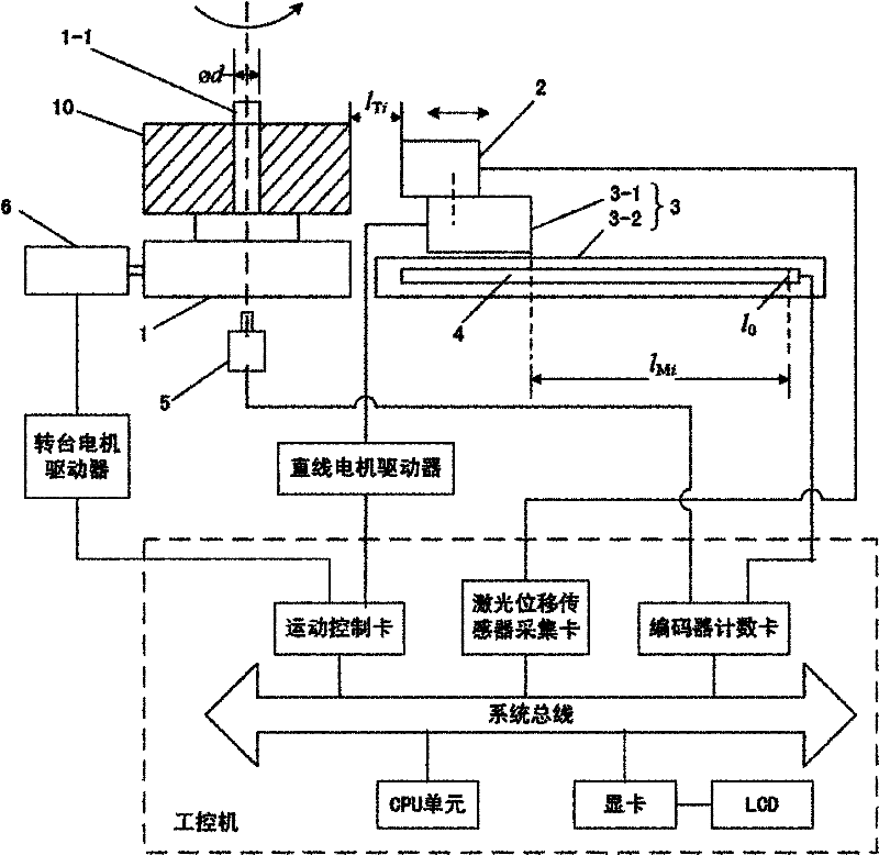
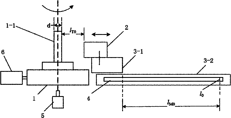
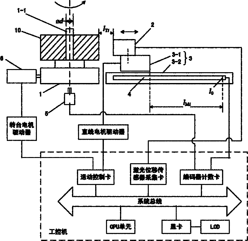
[0021] see Figure 1-2 , The cam profile detection device of this embodiment includes: a numerical control turntable 1 for driving the cam 10 to rotate horizontally and coaxially around a vertical axis 1-1, a linear motor 3 horizontally arranged on one side of the numerical control turntable 1, and The laser measuring head on the mover 3-1 of the linear motor 3 and on the side of the cam 10 2, the grating scale displacement sensor 4 for measuring the horizontal displacement of the mover 3-1, and the rotation of the cam 10 Angle encoder 5, and industrial computer; The industrial computer controls the motion of the numerically controlled turntable 1 and the linear motor 3, and is obtained based on the data measured by the laser measuring head 2, the grating scale displacement sensor 4, and the encoder 5 The outer contour data of the cam 10.

[0022] As an optimal embodiment, the center line of the stator 3-2 of the linear motor 3 and the laser output from the laser measuring head ...


PUM


Abstract

The invention provides a device for detecting cam profiles, which has the advantages of simple structure, high detection precision and higher efficiency. The device comprises a numerical control turntable, a linear motor, a laser measuring head, a grating scale displacement sensor, an encoder and an industrial personal computer, wherein the numerical control turntable is used for driving the cam to horizontally and coaxially rotate around a vertical mandrel; the linear motor is horizontally arranged on one side of the numerical control turntable; the laser measuring head is arranged on the active cell of the linear motor and at one side of the cam; the grating scale displacement sensor is used for measuring the horizontal displacement of the active cell; the encoder is used for detecting the rotation angle of the cam; and the industrial personal computer controls the numerical control turntable and the linear motor to act and obtains the outer profile data of the cam according to datameasured by the laser measuring head, the grating scale displacement sensor and the encoder.

Description

Technical field [0001] The invention relates to a cam profile detection device and a detection method thereof. Background technique [0002] Cam mechanisms are widely used in various automated machinery, precision instruments, automated control systems, etc. It is necessary to detect the cam with high precision and efficiency, and correctly process and evaluate its various errors, and feedback the quality information of the cam in a timely and fast manner. The traditional optical mechanical measuring instrument and manual data processing methods can no longer adapt to the wide range of cams. The use of automatic production lines is needed. With the rapid development of the automobile industry and engineering machinery and the continuous improvement of manufacturing technology, how to improve the detection accuracy and efficiency of cam processing accuracy is a technical problem to be solved in this field. Summary of the invention [0003] The technical problem to be solved by th...

Claims


Application Information

Patent Timeline
Patent Type & Authority Patents(China)
IPC IPC(8): G01B11/24G01B11/14
Inventor 丁仕燕干为民
Owner CHANGZHOU INST OF TECH
Why Eureka
Try Eureka