Lower disc assembly of grinding machine or polishing machine

A polishing machine and grinding machine technology, which is applied to the parts of grinding machine tools, grinding machine tools, grinding/polishing equipment, etc., can solve the problems of long transmission chain, excessive transmission chain gap, and increased auxiliary time for product pick-and-place, etc. To achieve the effect of ensuring parallelism and highlighting safety

Pending Publication Date: 2022-05-13
SHENZHEN SAPPHIRE AUTOMATION EQUIP
View PDF1 Cites 0 Cited by
  • Summary
  • Abstract
  • Description
  • Claims
  • Application Information

AI Technical Summary

Problems solved by technology

However, the working disk of this invention is driven by the motor to rotate through the first transmission assembly to realize multi-station polishing, because the first transmission assembly includes a belt drive and a reduction mechanism, the transmission chain is very long, and the gap accumulated in the transmission chain is too large to make it work. When the disc is stopped, it cannot be precisely positioned and locked, and the working disc shakes left and right on the station, which affects the polishing quality of the workpiece
[0004] In addition, because the position of the detachable main shaft cannot be precisely positioned, it is impossible to realize the positioning of the manipulator to pick and place the workpiece, which increases the auxiliary time for product pick-and-place and reduces the production efficiency.

Method used


Image

  • Lower disc assembly of grinding machine or polishing machine
  • Lower disc assembly of grinding machine or polishing machine
  • Lower disc assembly of grinding machine or polishing machine

Examples


Embodiment Construction

[0032] The following will clearly and completely describe the technical solutions in the embodiments of the present invention with reference to the accompanying drawings in the embodiments of the present invention. Obviously, the described embodiments are only some, not all, embodiments of the present invention. Based on the embodiments of the present invention, all other embodiments obtained by persons of ordinary skill in the art without making creative efforts belong to the protection scope of the present invention.

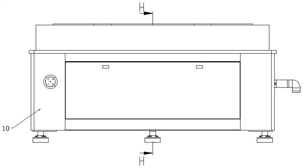
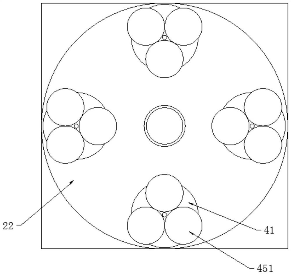
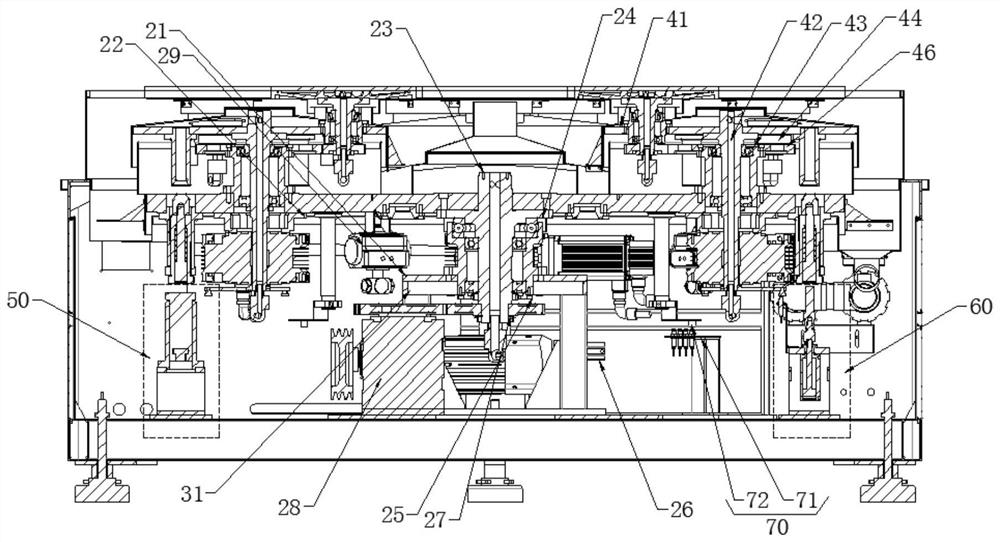
[0033] see Figure 1 to Figure 11 As shown, the present invention provides the following technical solutions: a lower plate assembly of a grinding machine or a polishing machine, including a frame 10, a lower plate assembly 40, a lower plate revolution assembly 20, a lower plate rotation assembly 30, a control circuit 70, and a tray fixing Mechanism 50 and pick-and-place material positioning mechanism 60.

[0034] Further, the lower plate revolution assembly ...


PUM


Abstract

The invention relates to a lower disc assembly of a grinding machine or a polishing machine, which comprises a rack, a lower disc assembly, a lower disc revolution assembly, a lower disc rotation assembly, a control circuit, a tray fixing mechanism and a material taking and placing positioning mechanism, the main tray comprises supporting holes with the same number as the lower tray assemblies. The lower disc assembly comprises an auxiliary tray, an auxiliary disc shaft, a bearing sleeve, a tray shaft driving gear and a lower disc assembly, the bearing sleeve is arranged in the supporting hole, the lower disc assembly is installed on the auxiliary tray, the auxiliary tray is fixed to the upper end of the tray shaft, the auxiliary disc shaft is supported by a bearing in the bearing sleeve, and the lower end of the auxiliary disc shaft is connected with the tray shaft driving gear. The tray shaft drives the gear and is driven by the lower tray rotation assembly. According to the tray positioning mechanism, the tray can abut against the plane position, in the machining process, the lower tray cannot sink when an upper tray conducts pressure machining on a workpiece, and the parallelism of a product in the machining process is guaranteed.

Description

technical field [0001] The invention relates to a grinding machine or a polishing machine, in particular to a lower plate assembly of a grinding machine or a polishing machine. Background technique [0002] Grinding machine / single-side polishing machine is suitable for processing ultra-thin hard and brittle material-shaped precision parts, and is the main equipment for plane processing of ultra-thin hard and brittle materials. Due to the particularity of processing ultra-thin hard and brittle materials, the equipment requires high processing Accuracy, the parallelism of the lower plate plays a vital role in the surface quality of the workpiece. In the traditional bottom plate structure, the revolution and rotation of multiple grinding discs are processed. It is a relatively optimized polishing method in the existing industry. It cannot load and unload products without stopping the machine. When the workpiece on one of the grinding discs is being processed When the processin...

Claims


Application Information

Patent Timeline
Patent Type & Authority Applications(China)
IPC IPC(8): B24B29/00B24B37/34B24B41/00
CPCB24B37/34B24B37/345B24B29/00B24B41/005
Inventor 范镜郑文洲李创坚张得意董成锋
Owner SHENZHEN SAPPHIRE AUTOMATION EQUIP
Why Eureka
Try Eureka