
Clamping mechanism

A technology of clamping mechanism and elastic sleeve, which is applied in the direction of clamping, workpiece clamping device, metal processing machinery parts, etc., can solve the problems of troublesome disassembly, lower work efficiency, and low precision of workpiece, and achieve convenient disassembly and installation, Improve work efficiency and avoid the effect of pinching the workpiece

Inactive Publication Date: 2015-04-29
浙江和良智能装备有限公司
View PDF4 Cites 16 Cited by
  • Summary
  • Abstract
  • Description
  • Claims
  • Application Information

AI Technical Summary

Problems solved by technology

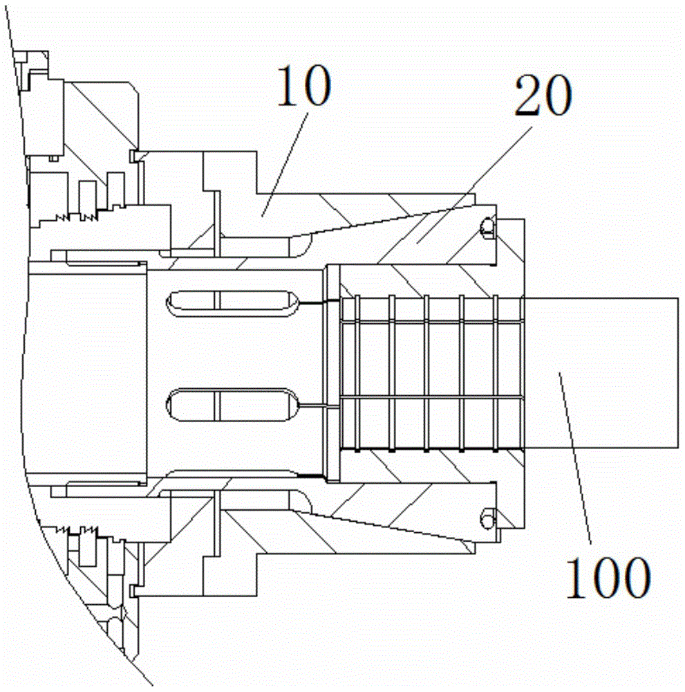
[0003] In the prior art, such as figure 1 As shown, a clamping device includes a sleeve part 10 for clamping a workpiece and a clamping seat 20. The clamping seat 20 is set on the outer end surface of the sleeve part 10, and the clamping seat 20 is driven by a driving device to clamp the sleeve. Cylinder 10, so as to clamp the workpiece, but there are still the following defects: the driving device drives one end of the clamping seat 20 to achieve clamping, the force acting on the sleeve 10 is uneven, and the force is directed toward the sleeve near the outer end surface. The cylinder parts 10 are gradually reduced, and the clamping force is unevenly distributed on the workpiece. On the one hand, the clamping of the workpiece is not in place. Due to insufficient clamping force, the processing of the workpiece is seriously affected, and the processed workpiece is low in accuracy or even scrapped. On the other hand, the uneven force will pinch the workpiece; (2) when processing different types of workpieces, the entire clamping head needs to be disassembled and replaced, which is troublesome to disassemble and complicated to install, greatly reducing work efficiency

Method used


Image

  • Clamping mechanism
  • Clamping mechanism
  • Clamping mechanism

Examples


Embodiment Construction

[0030] In order to make the purpose, technical solutions and advantages of the embodiments of the present invention more clear, the following will clearly and completely describe the technical solutions of the embodiments of the present invention in conjunction with the drawings of the embodiments of the present invention. Apparently, the described embodiments are some, not all, embodiments of the present invention. Based on the described embodiments of the present invention, all other embodiments obtained by persons of ordinary skill in the art without creative efforts shall fall within the protection scope of the present invention.

[0031] In describing the present invention, it is to be understood that the terms "upper", "lower", "front", "rear", "left", "right", "top", "bottom", "inner", "outer" ” and other indicated orientations or positional relationships are based on the orientations or positional relationships shown in the accompanying drawings, which are only for the...


PUM


Abstract

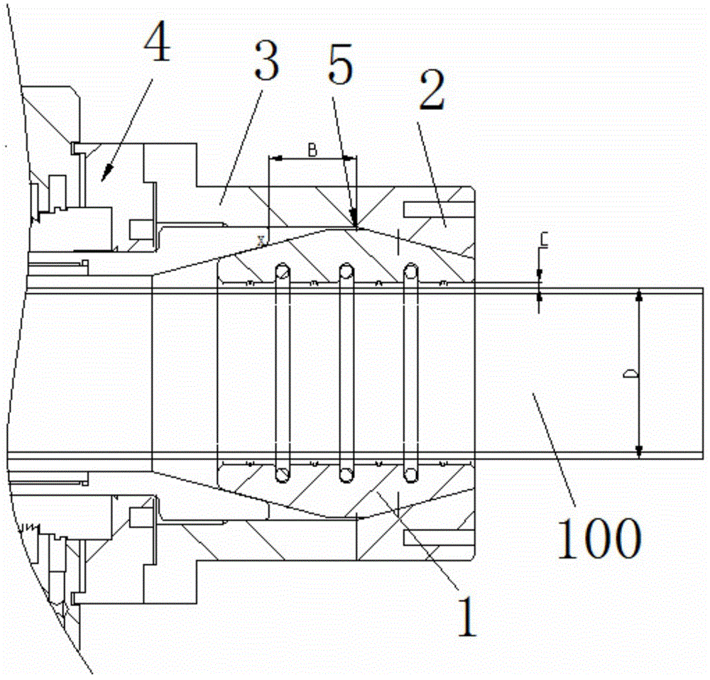
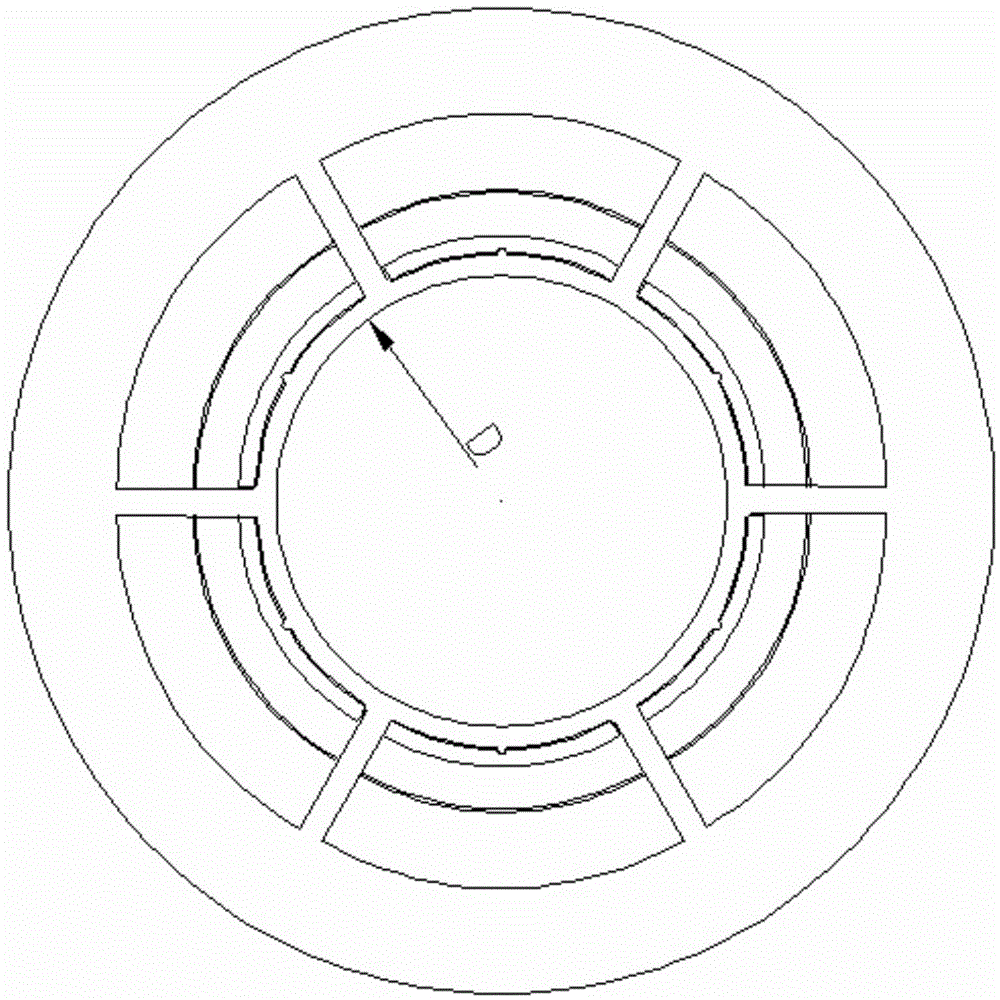
The invention discloses a clamping mechanism. The clamping mechanism comprises an elastic sleeve and a force application component, wherein the force application component is used for clamping and releasing the elastic sleeve which is used for clamping a workpiece. The middle of the elastic sleeve is provided with an operation cavity allowing placement of the workpiece, and the outer end face of the elastic sleeve is drum shaped. The force application component comprises a fixed seat, a moving seat and a driving device, the moving seat is matched with the fixed seat which is fixedly connected with equipment, the driving device drives the moving seat to move, and a tapered portion matched with the drum-shaped outer end face of the elastic sleeve are formed on the inner wall of each of the fixed seat and the moving seat. The driving device drives the moving seat to move forward to clamp the elastic sleeve, and the driving device drives the moving seat to move backward to release the elastic sleeve. The clamping mechanism has the advantages of simple structure, convenience in mounting and demounting and uniformity in workpiece clamping force.

Description

technical field [0001] The invention relates to the field of clamping, in particular to a clamping mechanism. Background technique [0002] In machining, many workpieces need to be fixed and positioned by clamping devices in the process of processing or measuring. With the continuous innovation of technology, the original manual clamping has developed to the current common mechanical clamping. The drive clamps and releases the workpiece. [0003] In the existing technology, such as figure 1 As shown, a clamping device includes a sleeve part 10 for clamping a workpiece and a clamping seat 20. The clamping seat 20 is set on the outer end surface of the sleeve part 10, and the clamping seat 20 is driven by a driving device to clamp the sleeve. Cylinder 10, so as to clamp the workpiece, but there are still the following defects: the driving device drives one end of the clamping seat 20 to achieve clamping, the force acting on the sleeve 10 is uneven, and the force is directed ...

Claims


Application Information

Patent Timeline
Patent Type & Authority Applications(China)
IPC IPC(8): B25B11/00
CPCB25B11/00B23Q3/00
Inventor 李良有张良
Owner 浙江和良智能装备有限公司
Learn More