Beer outlet valve of beer barrel

A beer keg and valve body technology, which is applied in the field of beer keg outlet valves, can solve problems such as complex operation and complex structure, and achieve the effects of simple operation, good stability and simple structure

Active Publication Date: 2014-01-22
TALOS TECH CORP
View PDF7 Cites 16 Cited by
  • Summary
  • Abstract
  • Description
  • Claims
  • Application Information

AI Technical Summary

Problems solved by technology

[0004] The air intake pipe of this kind of wine delivery mechanism is bent at right angles. One end of the air intake pipe is located above the body and is connected with the regulating valve, and the other end extends to the bottom of the beer barrel. The upper part of the body is connected with one end of the wine outlet pipe. The body has a fixed structure for fixing the intake pipe and the wine outlet pipe. The other end of the wine outlet pipe is connected with the wine outlet faucet. That is to say, at least two actions are required, one is to inflate the air source into the keg by controlling the regulating valve, and the pressure in the beer keg needs to be checked at any time, the other is to pull the switch handle and the pressure in the beer keg reaches the condition, In order to make the wine flow out of the beer keg, the operation is complicated; and when the control valve is inflated into the keg, the air pump, the first CO2 cylinder and the second CO2 cylinder are involved, and the structure is complicated.

Method used


Image

  • Beer outlet valve of beer barrel
  • Beer outlet valve of beer barrel
  • Beer outlet valve of beer barrel

Examples


Embodiment 1

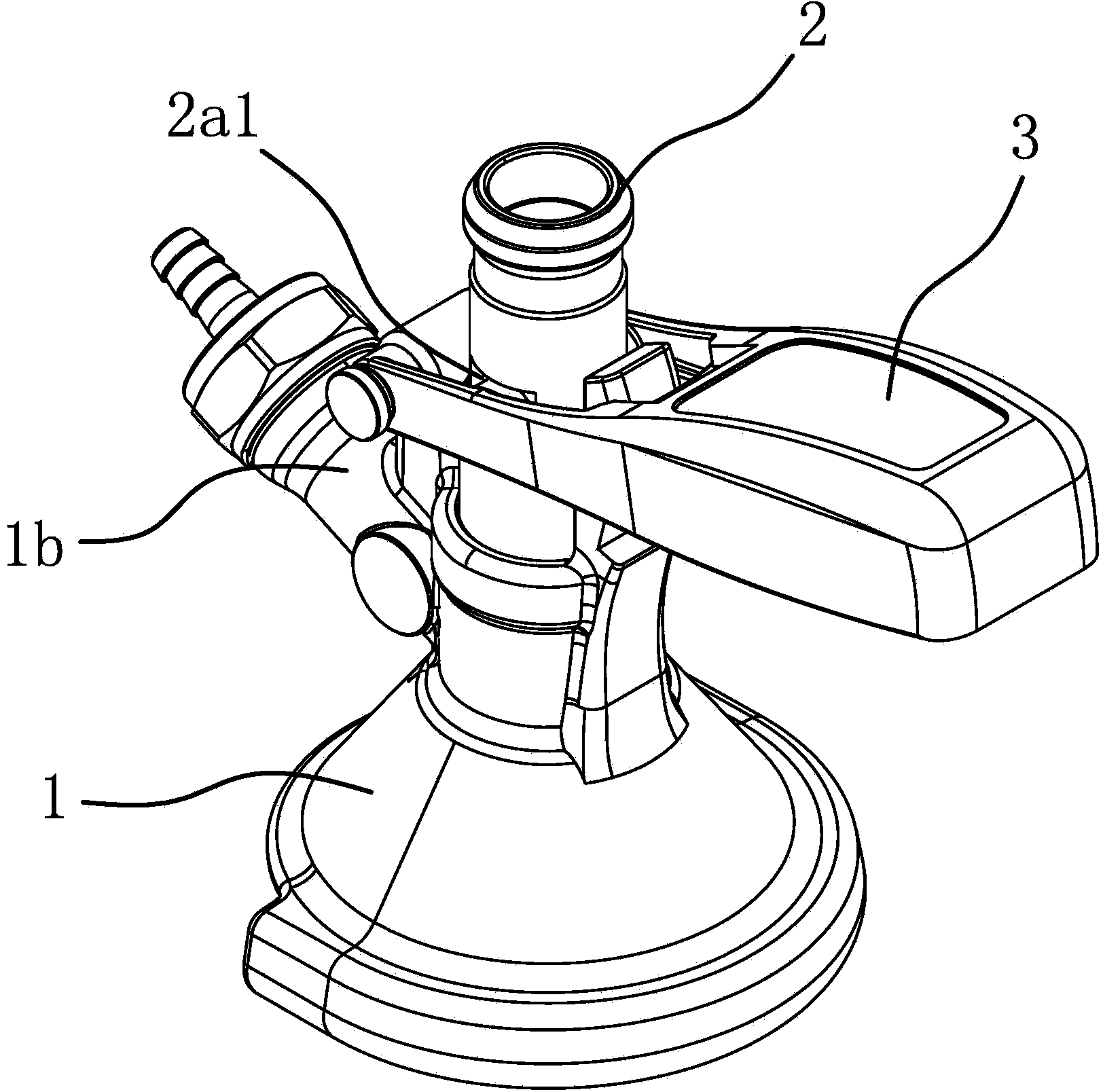
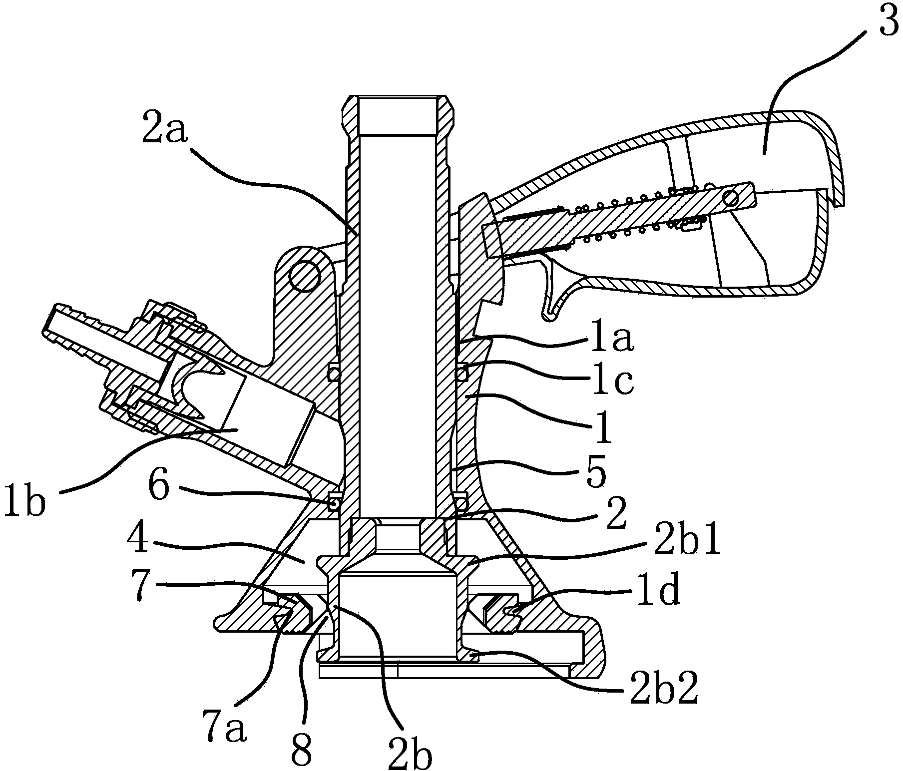
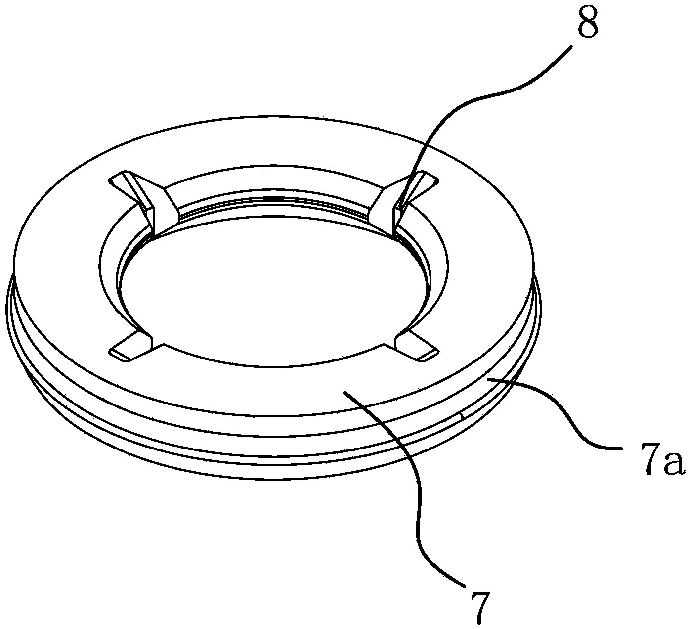
[0030] like figure 1 , 2 As shown, the wine outlet valve of the beer keg includes a valve body 1, a wine guide pipe 2, a handle 3, an air intake structure and a guide pad 7.

[0031] The center of the valve body 1 has a guide hole 1a penetrating in its axial direction, and the side of the valve body 1 has an air inlet pipe 1b, one end of the air inlet pipe 1b communicates with the guide hole 1a, and the other end is connected with the gas delivery device. There is a pair of seal ring seats 1c on the side wall of the guide hole 1a, one seal ring seat 1c is located above the connection between the intake pipe 1b and the guide hole 1a, and the other seal ring seat 1c is located at the connection between the intake pipe 1b and the guide hole 1a below. The bottom of the valve body 1 is in the shape of a conical cone to match the shape of the joint with the beer keg, and the inside of the bottom of the valve body 1 has an air outlet 4 that is consistent with its external shape, an...

Embodiment 2

[0035] The structure and principle of this embodiment are basically the same as that of Embodiment 1, the difference is that in this embodiment, the air intake structure includes the air inlet that is recessed in the middle of the wine guide tube 2 along its axial direction and the air inlet between the valve body 1 and the air intake pipe. A pair of sealing rings 6 between 1b, the air inlet of this kind of structure has a smaller area and is more convenient to process.


PUM


Abstract

The invention provides a beer outlet valve of a beer barrel, belongs to the technical field of beer barrel producing technology, and aims to solve the problems that the beer outlet mechanism of an existing beer barrel is complex in structure and tedious in operation. The beer outlet valve of the beer barrel comprises a valve body, a beer guide pipe and a handle. The center of the valve body is provided with a through guide hole, an air inlet pipe communicating with the guide hole is formed on the side portion of the valve body, the beer guide pipe is located at the guide hole and is connected with the valve body in a sealed manner, and an air outlet communicating with the interior of the beer barrel is formed between the bottom of the valve body and the beer guide pipe. The handle is hinged with the valve body and is connected with the beer guide pipe, and the side portion of the beer guide pipe is provided with an air inlet structure; when the handle drives the beer guide pipe to move downwards along the guide hole, and the air inlet pipe is allowed to be communicated with the air outlet through the air inlet structure. The beer outlet valve of the beer barrel has the advantages that air inflating and beer discharging can be implemented though operation for one time, and operations is simple and facilitated.

Description

technical field [0001] The invention belongs to the technical field of beer keg manufacturing, and relates to a wine outlet valve of a beer keg. Background technique [0002] Some beer machines currently on the market use the pressure of the beer keg itself to press the beer out. If the pressure inside the beer keg is not enough or leaks, the whole barrel of wine cannot be fully pressed out, resulting in waste. [0003] For this reason, people have made some improvements, and some have also applied for patents. For example, the Chinese patent literature discloses a beer machine [application number 201020138238.8; authorization announcement number: CN201704055U], which includes a body provided with a freezing chamber, and the freezing chamber is used The beer keg is placed on the beer keg, which is equipped with a wine outlet mechanism, which includes an air inlet pipe, a wine suction pipe and a wine outlet pipe. To the bottom of the beer keg, the upper end is connected to o...

Claims


Application Information

Patent Timeline
Patent Type & Authority Applications(China)
IPC IPC(8): B67D1/14
Inventor 邱迪林
Owner TALOS TECH CORP
Why Eureka
Try Eureka