Target material assembly manufacturing method

A manufacturing method and component technology, applied in the direction of manufacturing tools, semiconductor devices, welding/welding/cutting items, etc., can solve problems such as low welding efficiency, no welding process between ultra-high-purity nickel target and back plate, poor bonding strength, etc., to achieve The effect of improving welding efficiency, uniform and firm solder distribution, and high solder coverage

Active Publication Date: 2014-01-15
KONFOONG MATERIALS INTERNATIONAL CO LTD
View PDF5 Cites 16 Cited by
  • Summary
  • Abstract
  • Description
  • Claims
  • Application Information

AI Technical Summary

Problems solved by technology

[0006] The technical problem solved by the present invention is that the combination strength of the target material and the back plate in the prior art is poor, the welding efficiency is low, and there is no welding process between the ultra-high-purity nickel target material and the back plate

Method used


Image

  • Target material assembly manufacturing method
  • Target material assembly manufacturing method
  • Target material assembly manufacturing method

Examples


Embodiment Construction

[0032] The technical solution of the present invention will be described clearly and completely through specific embodiments below in conjunction with the accompanying drawings. Apparently, the described embodiments are only a part of the possible implementation modes of the present invention, not all of them. According to these embodiments, all other implementation manners that can be obtained by those skilled in the art without creative efforts belong to the protection scope of the present invention.

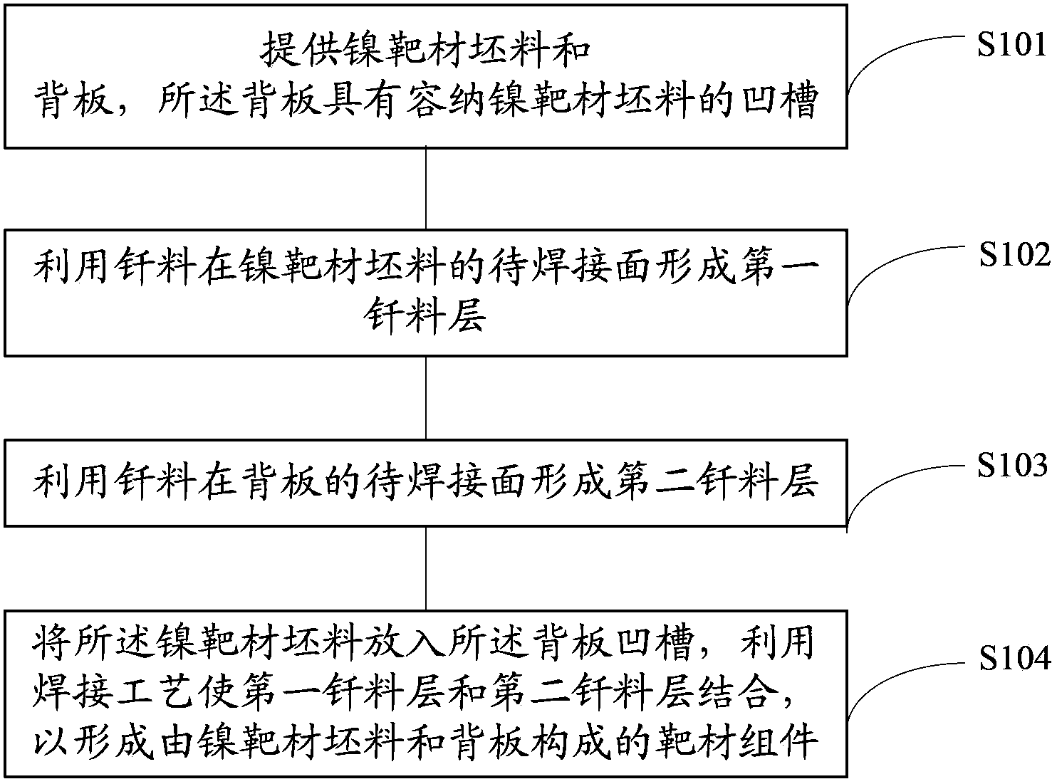
[0033] figure 1 is a schematic diagram of the production of the target in the present invention, combined with figure 1 As shown, the manufacturing method of the target comprises the following steps:

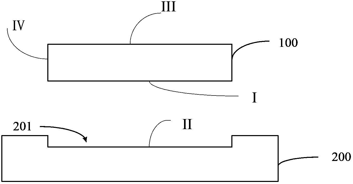
[0034] Step S101, providing a nickel target blank and a back plate, the back plate has a groove for accommodating the nickel target blank;

[0035] Step S102, using brazing filler metal to form a first brazing filler metal layer on the surface to be welded of the nickel target...


PUM


Abstract

A target material assembly manufacturing method comprises the steps of providing nickel target material blank and a back plate, wherein the back plate is provided with grooves for containing the nickel target material blank; utilizing brazing filler metal to form a first brazing filler metal layer on a face, to be welded, of the nickle target material blank; utilizing brazing filler metal to form a second brazing filler metal layer on a face, to be welded, of the back plate; placing the nickel target blank into the groove of the back plate, and utilizing the welding technology to combine the first brazing filler metal layer and the second brazing filler metal layer so as to form a target material assembly composed of the nickel target blank and the back plate. The target material assembly manufacturing method enables ultra-pure nickle target materials to be reliably combined with the back plate, is high in welding efficiency and small in welding defect rate, and can meet requirements of long-term stable production and utilization of target materials.

Description

technical field [0001] The invention relates to the field of semiconductor manufacturing, in particular to a manufacturing method of a target component. Background technique [0002] In the semiconductor industry, a target component is composed of a target blank that meets the sputtering performance, and a back plate that is combined with the target blank and has a certain strength. The back plate can play a supporting role when the target assembly is assembled to the sputtering base, and has the effect of conducting heat. [0003] In the existing process, the working environment of the target assembly is relatively harsh. For example, in the sputtering process, the working temperature of the target assembly is relatively high, such as 300°C to 500°C; in addition, one side of the target assembly is flushed to cool The water is strongly cold while the other side is at 10 -9 In the high vacuum environment of Pa, a huge pressure difference is formed on the upper and lower sid...

Claims


Application Information

Patent Timeline
Patent Type & Authority Applications(China)
IPC IPC(8): B23K1/00
CPCB23K1/0016B23K1/19B23K1/20B23K1/206B23K2101/40B23K2103/18
Inventor 姚力军相原俊夫大岩一彦潘杰王学泽何梅
Owner KONFOONG MATERIALS INTERNATIONAL CO LTD
Why Eureka
Try Eureka