Electrode support structure assemblies

a technology of support structure and electrode, which is applied in the field of electromechanical support structure assemblies, can solve the problems of limiting, corrals, and difficult for the electrode support structure to collapse evenly, and achieves the effects of less stress, less electrode distribution, and less stress

Active Publication Date: 2013-07-04
ST JUDE MEDICAL ATRIAL FIBRILLATION DIV
View PDF11 Cites 204 Cited by
  • Summary
  • Abstract
  • Description
  • Claims
  • Application Information

AI Technical Summary

Benefits of technology

[0012]It is desirable to provide an electrode support structure assembly that can include an element joining the distal end of each of the plurality of splines that is configured to provide freedom for each of the plurality of splines to move independently along an axis of the electrode support structure. This may help ensure that the splines are configured to straighten evenly when the electrode support structure is collapsed. It is also desirable to provide an electrode support structure assembly that can include an element joining the distal end of each of the plurality of splines that is configured to provide freedom for each of the plurality of splines to articulate relative to an axis of the electrode support structure such that each of the plurality of splines can be positioned at numerous angles relative to the axis of the electrode support structure in order to minimize stress imparted at the distal end of the electrode support structure during collapse and / or expansion. It is also desirable to provide an improved electrode arrangement that may provide more uniform electrode distribution when the electrode support structure is in its deployed or expanded state, while at the same time providing a smaller profile when in a collapsed state so as prevent electrode to electrode short circuits. It is also desirable to provide an electrode support structure that can be configured to allow for free, uniform axial displacement even if the electrode support structure is being diametrically constrained in some way.

Problems solved by technology

This lesion disrupts undesirable cardiac activation pathways and thereby limits, corrals, or prevents errant conduction signals that can form the basis for arrhythmias.
However, it may be difficult for the electrode support structure to collapse evenly if manufacturing variances have resulted in differences in the individual lengths of the splines.
It may also be difficult for the electrode support structure to collapse evenly if one or more of the splines have experienced a change in length relative to the remainder of the splines, such as during manipulation of the electrode support structure around a curve, for example.
Continued collapse or multiple collapses of the electrode support structure can potentially cause fatigue at the point of the protrusion or “loop” and ultimately fracture the spline.
Moreover, when the distal ends of the splines are fixed in place (e.g., mounted between two pieces of tubing), the distal flexibility of the splines may be limited, thereby adversely impacting the collapsibility of the electrode support structure.
In addition, stress imparted at the distal end of the electrode support structure during collapse and / or expansion of the electrode support structure can also result in the failure of any strut or other element that may be configured to join the distal ends of the splines together.
Additionally, when the electrode support structure is in an expanded state, electrode distribution may not be uniform in accordance with some electrode arrangements.
Moreover, during collapse of the electrode support structure (e.g., when the electrode support structure is emerging from or being retracted into a delivery sheath), some electrode arrangements may possibly result in electrode to electrode contact and / or short circuits, which may cause electrode wear and / or limit electrode functionality.
In addition, some electrode arrangements may not minimize the profile of the electrode support structure during collapse of the electrode support structure, which can result in electrode damage when the electrode support structure is being delivered through the delivery sheath, especially when being delivered through a tortuously angulated pathway.
An expander will not generally allow for free axial movement of the electrode support structure if the electrode support structure is being diametrically constrained in some way.

Method used


Image

  • Electrode support structure assemblies
  • Electrode support structure assemblies
  • Electrode support structure assemblies

Examples


first embodiment

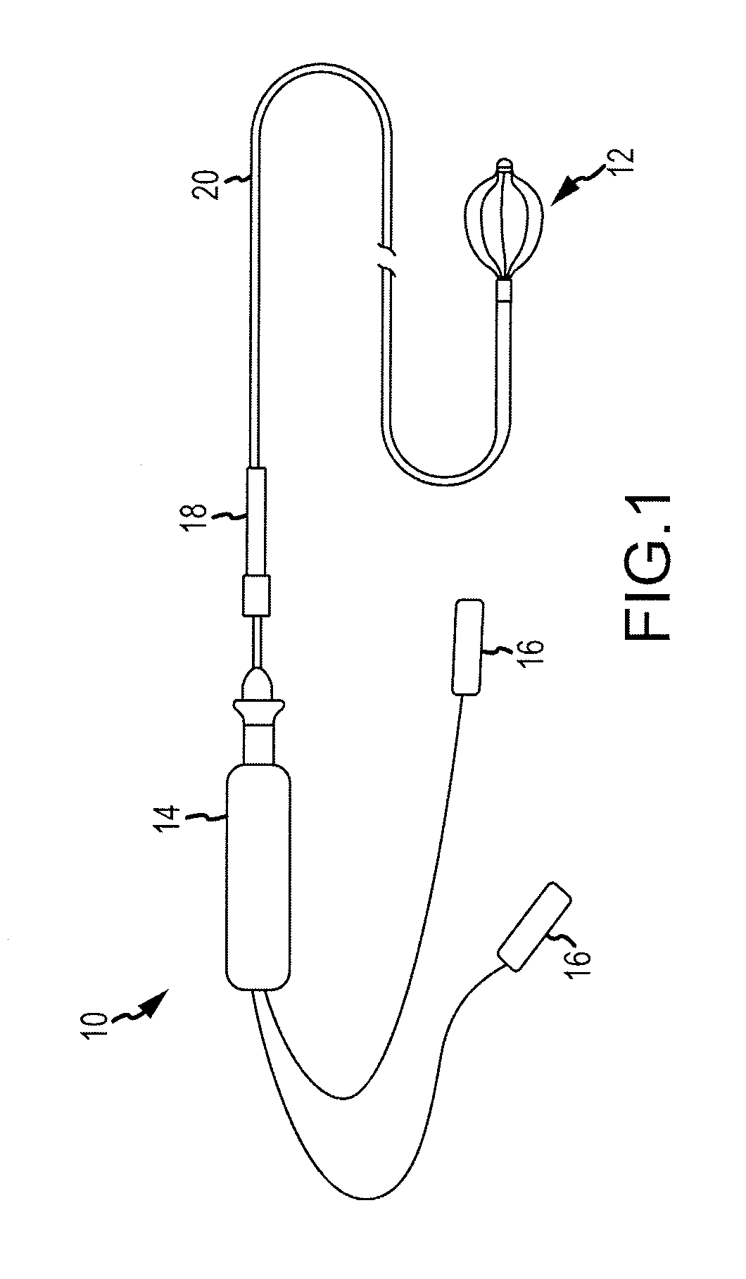
[0036]Referring now to FIG. 1, a side view of an intracardiac catheter system 10 employing an electrode support structure assembly 12 in accordance with the disclosure is generally illustrated. The catheter system 10 includes a handle 14 and connectors 16 disposed proximal to the handle 14 for making electrical connections to a visualization, navigation, and / or mapping system (not shown) such as those systems available under the name ENSITE NAVX™ (aka ENSITE™ Classic as well as newer versions of the ENSITE™ system, denoted as ENSITE VELOCITY™) and available from St. Jude Medical, Inc. The handle 14 can have a uni-directional design, a bi-directional design, or any other suitable design and be accordingly configured to steer the electrode support structure assembly 12. The catheter system 10 can also include an introducer 18 located distally of the handle 14 that may be used to deliver an elongated catheter body 20 into the body of a patient, through a hemostasis valve of another, lo...

second embodiment

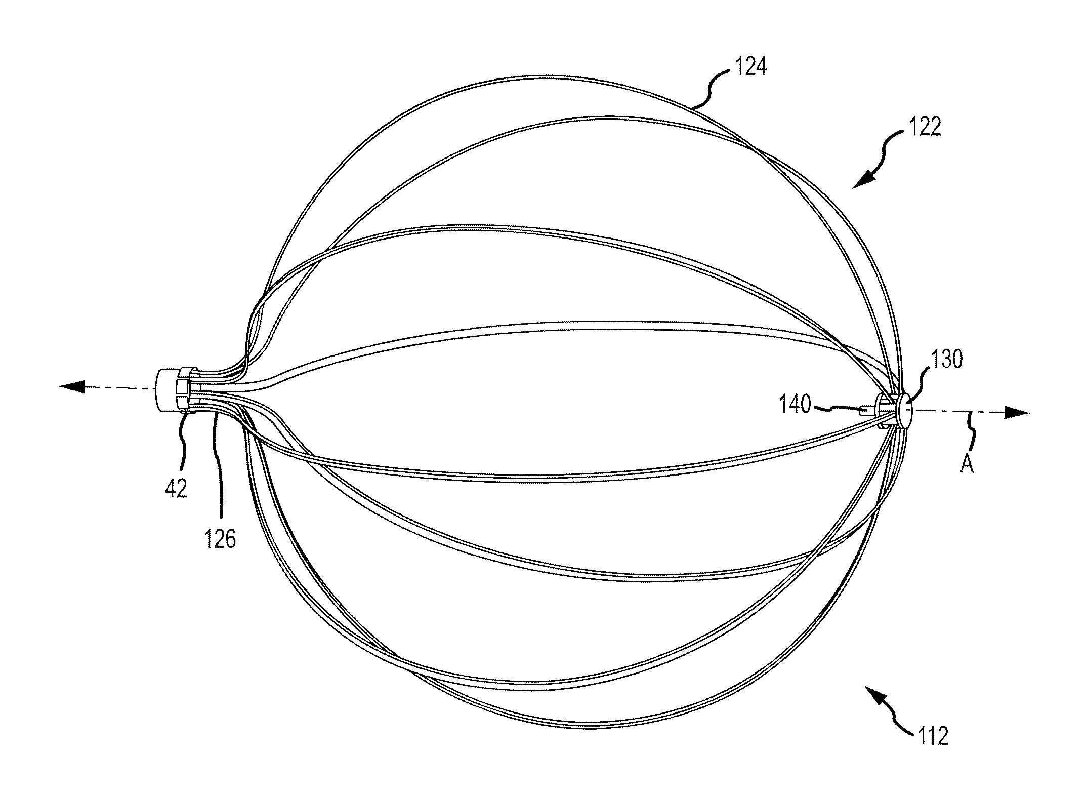
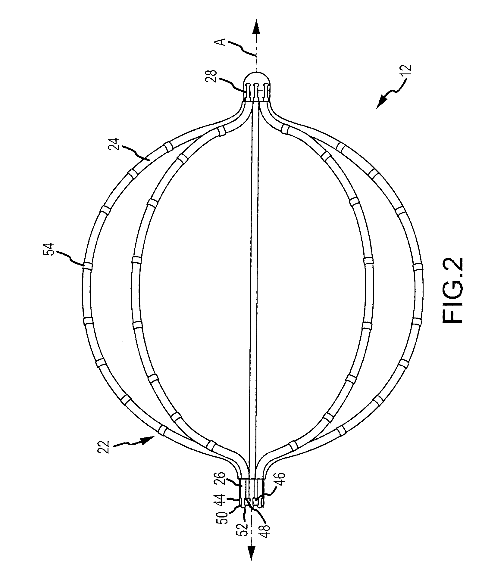
[0046]Referring now to FIGS. 4-9, an electrode support structure assembly 112 in accordance with the disclosure is generally illustrated. The electrode support structure assembly 112 can be similarly mounted to the distal end of the elongated catheter body 20 (see FIG. 1) and can be substantially identical to electrode support structure assembly 12 described above except for differences in the proximal end portion of each of the plurality of splines and differences in the elements configured to join the distal end portions of the splines as described hereinbelow. The electrode support structure assembly 112 can further comprise one or more electrodes (such as electrodes 54 shown in FIG. 2) supported by one or more of the plurality of splines 124. For example, one or more of the plurality of splines 124 can have one or more electrodes (such as electrodes 54 shown in FIG. 2) mounted on the non-conductive covering of each of the plurality of splines 124 in accordance with various embod...

third embodiment

[0055]In accordance with the disclosure, each spline 241, 1241, may be symmetric with each adjacent spline 242, 1242. In other words, each spline 241, 1241, 242, 1242 can have the same electrode layout when flipped proximal end to distal end. In accordance with such an arrangement, a first distance dist1 between a distal-most electrode 54d of the first plurality of electrodes 541 and a distal end 281 of the first spline 241, 1241 is substantially the same as a second distance dist2 between a proximal-most electrode 54p of the second plurality of electrodes 542 and a proximal end 262 of the second spline 242, 1242. Although these particular electrode arrangements are mentioned and illustrated in detail, there may be additional electrode arrangements that be utilized in accordance with various embodiments of the disclosure. For example and without limitation, spacing between electrodes 54 can vary based on the length of splines 241, 1241, 242, 1242 or the desired distance from the pro...


PUM


Abstract

An electrode support structure assembly is provided comprising an electrode support structure including a plurality of splines. Each of the plurality of splines can have a proximal end portion and a distal end portion. The assembly further comprises a first element defining an axis and comprising an outer surface. The outer surface comprises a plurality of slots configured to receive the distal end portion of each of the plurality of splines. The first element is configured such that the distal end portion of each of the plurality of splines may move with respect to each slot. In accordance with some embodiments, the distal end portion of each of the plurality of splines comprises a section configured for engagement with the first element, wherein the section comprises a shoulder.

Description

BACKGROUND OF THE INVENTION[0001]a. Field of the Invention[0002]The instant disclosure relates generally to electrode support structure assemblies. In particular, the instant disclosure relates to electrode support structure assemblies for basket catheters including a plurality of splines.[0003]b. Background Art[0004]Electrophysiology catheters are used in a variety of diagnostic, therapeutic, and / or mapping and ablative procedures to diagnose and / or correct conditions such as atrial arrhythmias, including for example, ectopic atrial tachycardia, atrial fibrillation, and atrial flutter. Arrhythmias can create a variety of conditions including irregular heart rates, loss of synchronous atrioventricular contractions and stasis of blood flow in a chamber of a heart which can lead to a variety of symptomatic and asymptomatic ailments and even death.[0005]Typically, a catheter is deployed and manipulated through a patient's vasculature to the intended site, for example, a site within a p...

Claims


Application Information

Patent Timeline
Patent Type & Authority Applications(United States)
IPC IPC(8): A61B5/042A61B18/00
CPCA61B18/1492A61B2018/00267A61B2018/1475A61B2562/16A61B5/6859A61B5/6858A61B5/0422A61B2218/002A61B5/287
Inventor JUST, DALE E.TEGG, TROY T.JOHNSON, THEODORE A.
Owner ST JUDE MEDICAL ATRIAL FIBRILLATION DIV
Why Eureka
Try Eureka