High power factor isolated buck-type power factor correction converter

a technology of power factor and correction converter, which is applied in the direction of electric variable regulation, process and machine control, instruments, etc., can solve the problem of no reverse recovery, and achieve the effect of increasing efficiency, reducing turns ratio, and increasing power factor

Active Publication Date: 2009-11-26
MYPAQ HLDG LTD
View PDF99 Cites 109 Cited by
  • Summary
  • Abstract
  • Description
  • Claims
  • Application Information

AI Technical Summary

Benefits of technology

[0026]The present invention overcomes the problems of using buck-type topologies through two different novel methods. The first novel method consists of adding a high-turns-ratio output tap switch to the isolation transformer. The high-turns-ratio output tap switch is coupled through a rectifier to the output during the portions of the input sinewave half-cycle, which are low in amplitude. This high-turns-ratio output tap switch allows the single-stage isolated buck-type converter to operate over a much larger portion of the input sinewave, but also allows the converter to operate at high-efficiency over the majority of the input sinewave.
[0027]The single-stage isolated buck-type converter with tap switch provides many advantages over conventional AC-to-DC power converters. First, the converter provides power factor correction and isolation in a single stage. Second, the tap switch enables the isolated buck-type converter to draw current from the AC source for a larger portion of the sinewave, thus increasing the power factor. Third, the tap switch allows the converter to operate with a lower turns ratio for the majority of the power transfer, thus increasing efficiency. Fourth, the tap switch can be configured to turn on and off in response to an input voltage set point that varies with the rms voltage of the input in such a way as to minimize component stress of the semiconductor switches and passive components of the converter. Fifth, the tap-switch, by enabling the use of isolated buck-type converters in PFC applications, enables all of the advantages of isolated buck-type converters in these applications such as soft-switching, fully resonant converters, lower voltage switches, lower EMI, and a fully utilized flux range for the isolation transformer. It will become apparent to those skilled in the art that additional advantages are provided in view of the power converter description provided herein.
[0028]The second novel method uses two single-stage isolated buck-type converters with inputs connected in series across the rectified AC line. The isolated outputs from these converters are combined to a single isolated output through a rectifier. When the input rectified sinewave half-wave is low in amplitude, one of the two converters is shorted, thereby placing the other of the two converters directly across the line. The net effect is to double the voltage across the input of the converter that is still operating. Shorting of one of the two converters can be accomplished either by the addition of another semiconductor switch across that converter (for the case of forward converters), or by shorting all of the input semiconductor switches for that converter (for bridge and push-pull converters). The power converter of the second method provides similar advantages as the power converter of the first method, without using a tap switch.

Problems solved by technology

Conventional boost-type power factor correction circuits often require an expensive high-voltage Schottky diode, such as a Silicon Carbide diode, to mitigate reverse recovery losses.
Second, in cases in which the isolated buck-type converter utilizes soft-switching, such as the fully-resonant embodiments, the output diodes of the isolated converter are switched at zero current, so there is no reverse recovery.

Method used


Image

  • High power factor isolated buck-type power factor correction converter
  • High power factor isolated buck-type power factor correction converter
  • High power factor isolated buck-type power factor correction converter

Examples


first embodiment

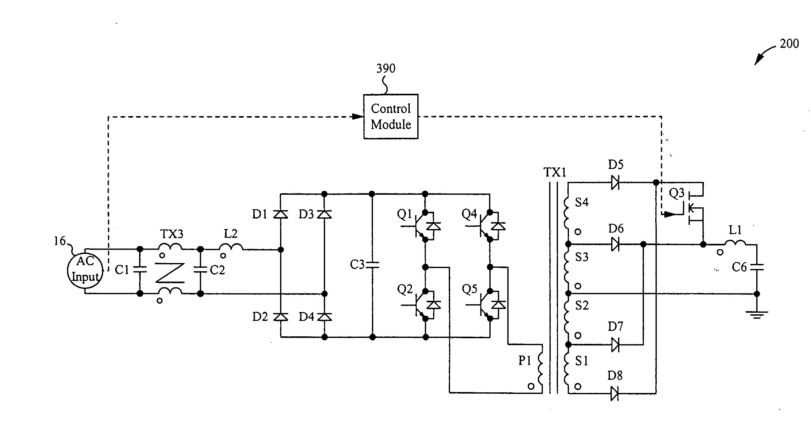
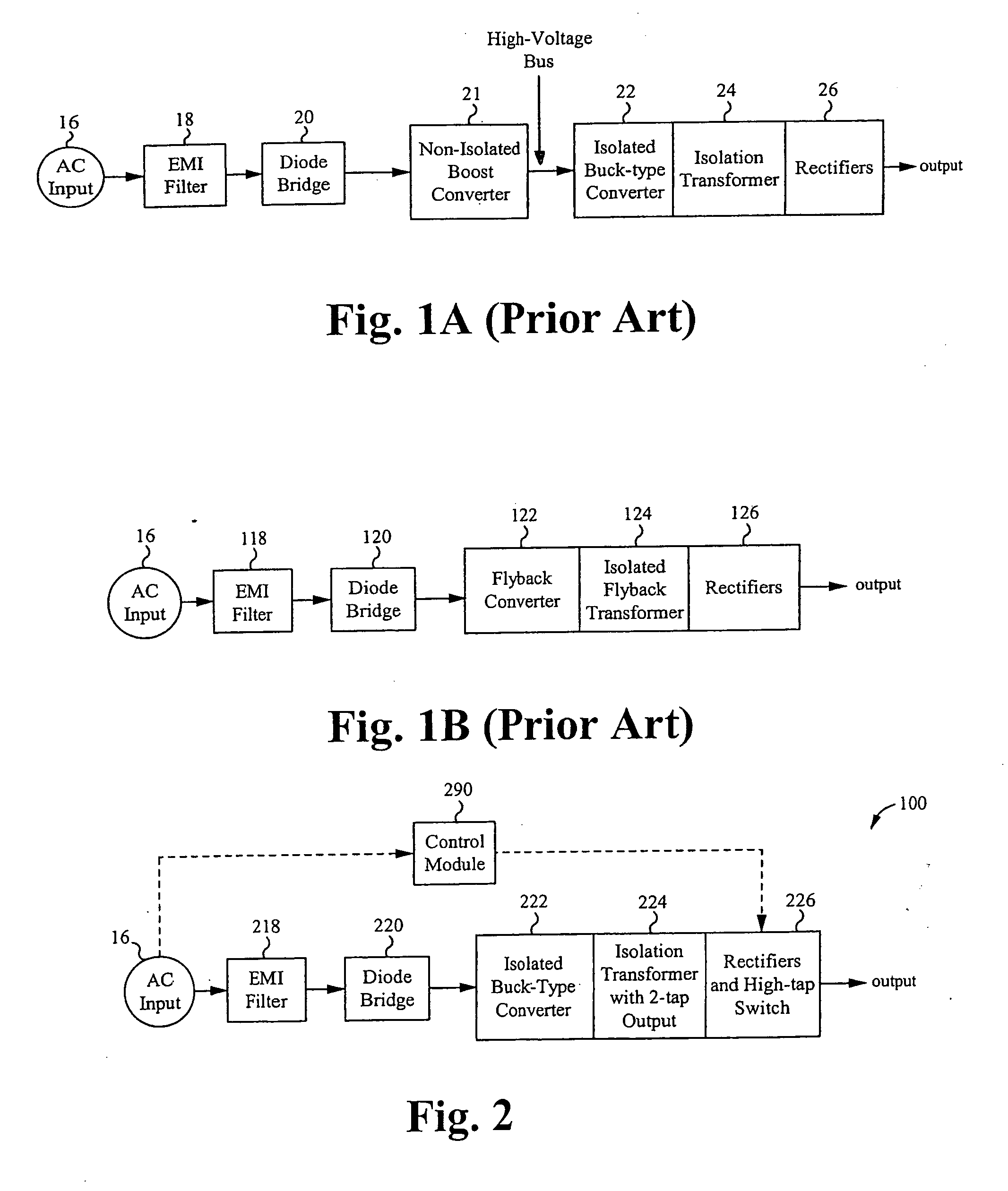
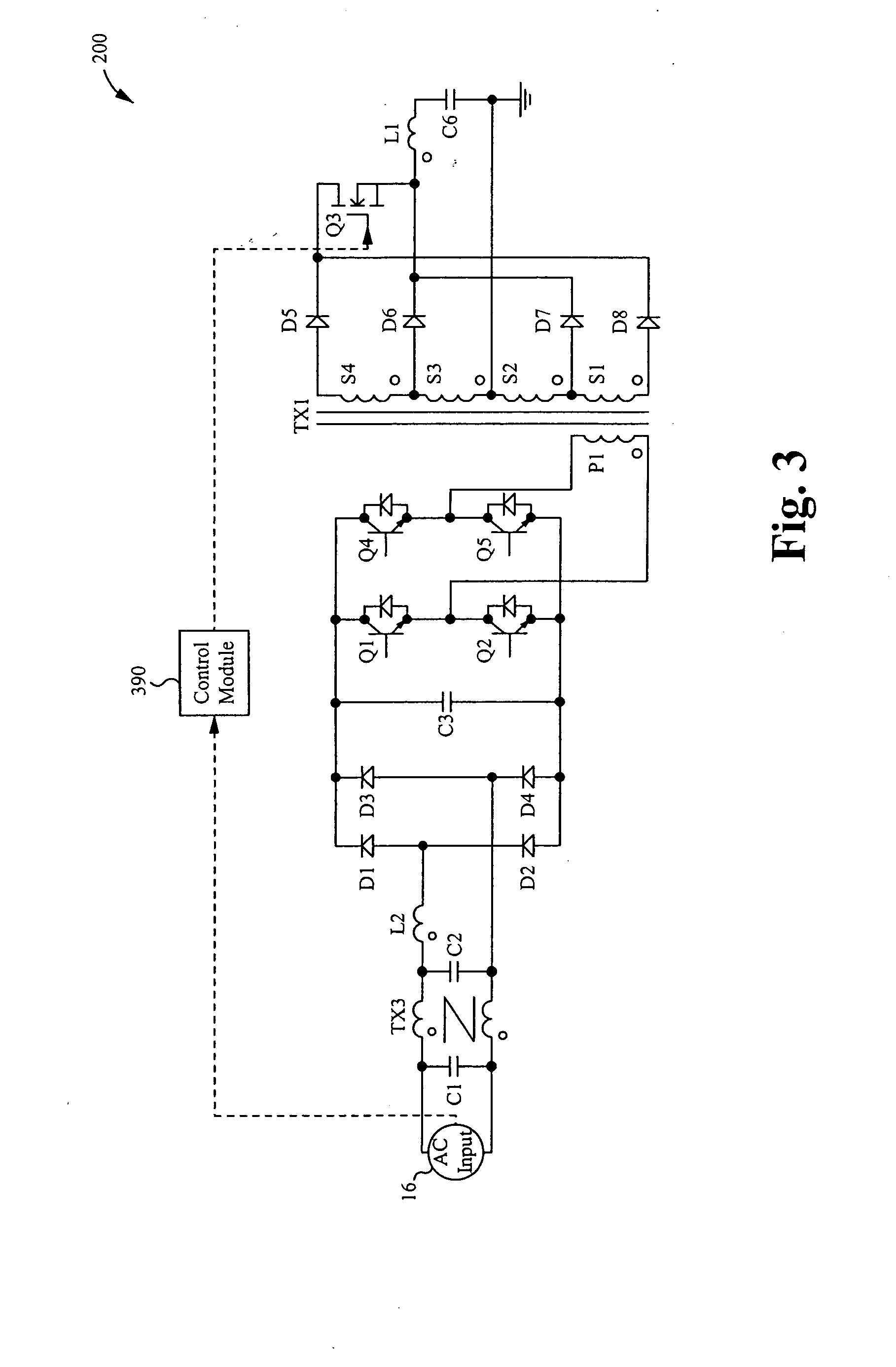
[0046]The power converter is configured to receive an AC input, to provide power factor correction, and to output an isolated DC voltage. In a first embodiment, the power converter includes an isolated buck-type converter with an isolation transformer. A rectifier, a tap switch, and a bulk storage capacitor are coupled to an output of the isolation transformer.

[0047]The isolated buck-type converter draws current from an AC input line when the input voltage scaled by the turns ratio of the isolation transformer exceeds the output voltage. When the rectified AC input line is at a low voltage part of the sinewave, the tap switch is turned on, thus increasing the effective turns-ratio from input to output of the transformer. The isolated buck-type converter is thus able to draw current during the low voltage part of the sinewave. When the rectified AC input line is at the high voltage part of the sinewave, the tap switch is turned off, thus instantly decreasing the effective turns-ratio...

second embodiment

[0074]In a second embodiment, the power converter includes two isolated buck-type converters, each with an isolation transformer and a rectifier coupled to an output of the isolation transformer. Each rectifier is coupled to a common output filter that includes a bulk storage capacitor. The voltage across the bulk storage capacitor provides an isolated DC output voltage of the power converter.

[0075]The two isolated buck-type converters have inputs tied in series across the full-wave rectified sinewave input. Rectifiers at the output of each isolated converter are connected to a common output capacitor. The series operation of the isolated converters is self-regulating because if the input voltage of one of the series converters drops, the output voltage of that converter drops, causing that converter to draw less power and thereby increase its input voltage. During the high-voltage part of the input AC sinewave, both of the series converters operate. During the low-voltage part of t...


PUM


Abstract

A regulated power factor corrected power supply apparatus is provided. The apparatus includes an input rectifier circuit for receiving an input AC voltage and outputting a full-wave rectified DC voltage. A single-stage isolated buck-type converter is coupled with the input circuit. The converter circuit comprises an isolated buck-type converter circuit including an isolation transformer. An output rectifier and semiconductor tap switch are coupled to a secondary winding of the isolation transformer. The tap switch couples a larger portion of the secondary winding to an output bulk capacitor during the portions of the input sinewave half-cycle, which are low in amplitude. The tap switch enables the single-stage isolation buck-type converter to operate over a much larger portion of the input sinewave, but also allows the converter to operate at high-efficiency over the majority of the input sinewave.

Description

FIELD OF THE INVENTION[0001]The present invention relates to power converters. More particularly, the present invention relates to a high power factor isolated buck-type power factor correction converter.BACKGROUND[0002]A power supply or power converter converts one form and voltage of electrical power to another desired form and voltage. AC-to-DC power supplies convert alternating current voltage, for example 115 or 230 volt alternating current (AC) supplied by a utility company, to a regulated direct current (DC) voltage. DC-to-DC power supplies convert DC voltage at one level, for example 400V, to another DC voltage, for example 12V.[0003]A variety of different DC-to-DC power converter configurations are currently in use, most of which are variations of a buck converter, a boost converter, and a buck-boost converter. Some variations of buck converters, referred to as isolated buck-type converters, include an isolating transformer. Some versions of isolated buck-type converters in...

Claims


Application Information

Patent Timeline
Patent Type & Authority Applications(United States)
IPC IPC(8): H02M3/335H02M3/00
CPCY02B70/126H02M1/4241Y02B70/10Y02P80/10
Inventor JUNGREIS, AARON
Owner MYPAQ HLDG LTD
Why Eureka
Try Eureka