Turbine device with variable flows

A flow and turbine technology, used in gas turbine devices, engine components, machines/engines, etc., can solve problems such as poor reliability and low efficiency, and achieve the effects of good inheritance, simple volute structure, and high reliability.

Active Publication Date: 2011-09-21
康跃科技(山东)有限公司
View PDF3 Cites 7 Cited by
  • Summary
  • Abstract
  • Description
  • Claims
  • Application Information

AI Technical Summary

Problems solved by technology

[0009] The problem to be solved by the present invention is to provide a simple structure, low cost, reliable operation, which can be used in the vaneless volute, in the small flow A variable flow turbine device that has high efficiency and acceleration response and can effectively take into account the efficiency and flow capacity of large flow

Method used


Image

  • Turbine device with variable flows
  • Turbine device with variable flows
  • Turbine device with variable flows

Examples


Embodiment 1

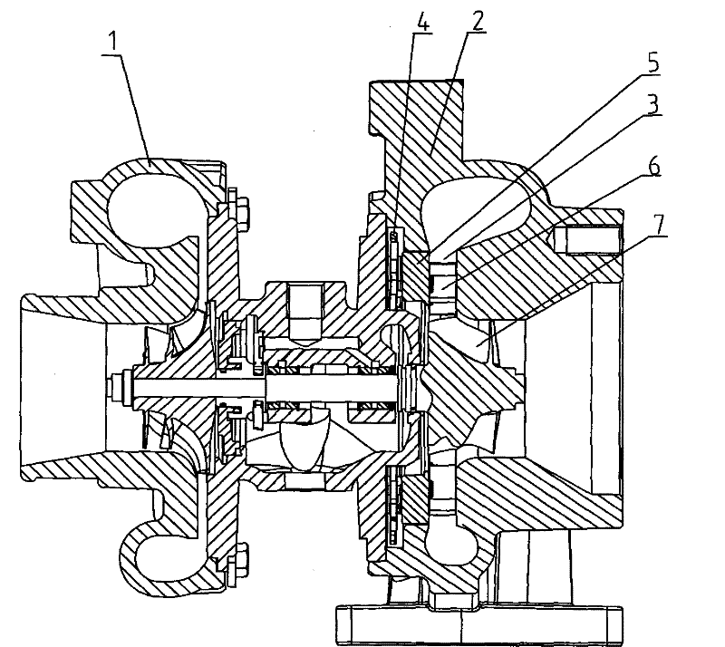
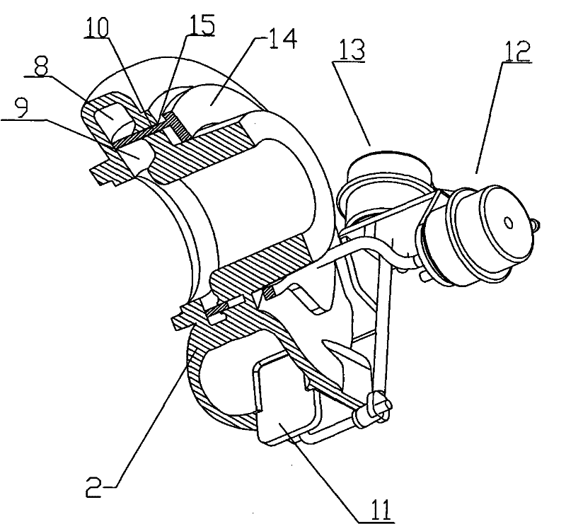
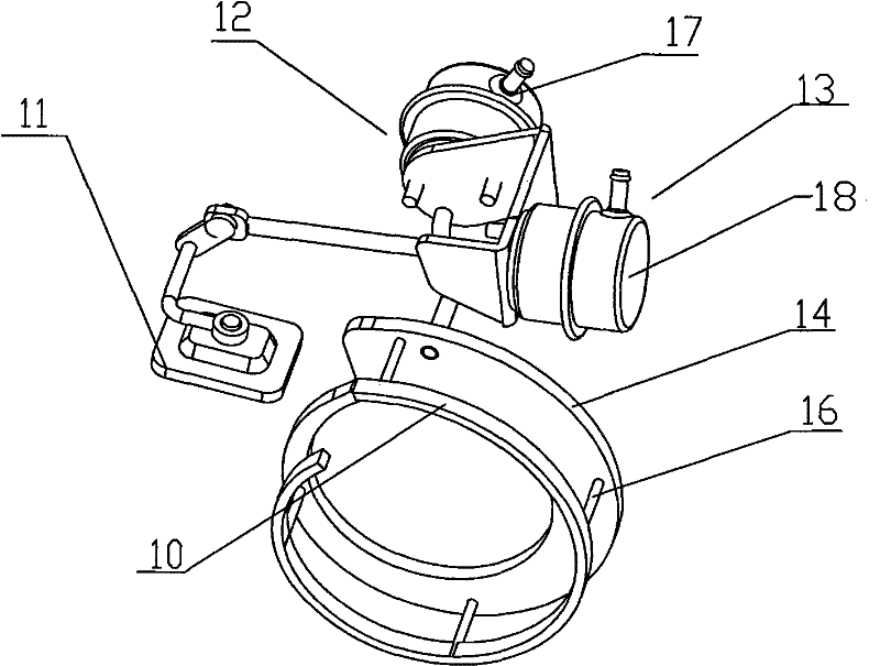
[0055] Embodiment 1, as attached figure 2 And attached image 3 As shown, a variable flow turbine device includes a volute 2, and the volute 2 is provided with an air intake channel; the air intake channel is provided with a partition wall 19 and a movable baffle with an arc-shaped transverse section. 10. The moving baffle 10 can move axially along the volute 2 in the air intake passage; one end of the moving baffle 10 protrudes from one side of the volute 2 and is connected with a moving baffle control device 12; when moving When the other end of the baffle 10 moves to the other side of the volute 2 , the moving baffle 10 separates the volute 2 into a volute outer flow channel 8 and a volute inner flow channel 9 that do not communicate with each other.

[0056] The volute outer channel 8 and the volute inner channel 9 are arranged in parallel, and the transverse section of the movable baffle 10 is straight.

[0057] A sliding slot 15 is provided on the volute 2 at a positi...

Embodiment 2

[0067] Embodiment 2, the difference between this embodiment and embodiment 1 is that, as Figure 6 As shown, the volute outer flow channel 8 and the volute inner flow channel 9 are arranged alternately. 20 is arranged longitudinally, the transverse section of the moving baffle 10 is a straight plate type, the moving baffle 10 is perpendicular to the flow channel vent 20, and is used to separate the volute outer flow channel 8 and the volute inner flow channel 9, and the moving baffle plate Under the action of the control mechanism, it can move along the axial direction of the volute, so as to realize the selection of different flow channels in the volute and the control of the gas flow distribution. According to the different shapes of the volute, the position and shape of the movable baffle 10 and its control mechanism can be designed specifically to meet the requirements of the variable channel of the volute.

Embodiment 3

[0068] Embodiment 3, the difference between this embodiment and embodiment 2 is that Figure 7 As shown, the transverse section of the movable baffle 10 is L-shaped, and the cross-sectional width A of the bottom transverse part is greater than or equal to the cross-sectional width B of the vertical part. 20 is opened, so that the gas in the outer channel 8 of the volute flows into the inner channel 9 of the volute under the guidance of the moving baffle 10, reducing the velocity component in the axial direction of the gas flowing into the inner channel 9 of the volute, and reducing the connection with the volute The blending of the airflow in the inner runner 9 reduces flow loss, improves the efficiency of the turbine, and can reduce the radial size of the turbine, which is beneficial to the installation of the turbine on the engine.

[0069] Under the action of the movable baffle control mechanism, the movable baffle 10 can move along the axial direction of the volute, so as ...


PUM


Abstract

The invention discloses a turbine device with variable flows. The turbine device provided by the invention comprises a volute, wherein the volute is provided with an air inflow path; the air inflow path is internally provided with a separation wall and a mobile baffle with an arc-shaped cross section; the mobile baffle can axially move along the volute in the air inflow path; one end of the mobile baffle extends out from one side of the volute and is connected with a control device of the mobile baffle in a transmission mode; when the other end of the mobile baffle moves to the other side of the volute, the mobile baffle is used for dividing the volute into an internal volute flow path and an external volute flow path which are not communicated mutually; and the control device of the mobile baffle drives the mobile baffle to move upwards in the spanwise direction of the volute so as to change the flow allocation proportion of the internal volute flow path and the external volute flow path. The volute is simple in structure, good in inheritance, low in cost and easy to quickly realize engineering, and can be used for solving the problems in reliability and efficiency of the existing variable geometry turbine-compressor with a vaned nozzle and the problem of lower efficiency of a variable geometry compressor without a vaneless volute.

Description

technical field [0001] The present invention relates to a variable cross-section supercharger, in particular to a variable-flow turbine device with a movable baffle that satisfies the performance requirements of each working condition of the engine by cooperating between flow channels of different cross-sections. It belongs to the field of internal combustion engines. technical background [0002] With the increasingly stringent emission regulations, it is required that the supercharger must have the function of adjusting the boost pressure and exhaust pressure, so the variable cross-section supercharger has become the focus of research and development at home and abroad. The existing variable cross-section superchargers that are widely used are all carried out on the nozzle ring with vanes. There are mainly two schemes. Among them, the rotary vane type is to adjust the angle (VNT) of the nozzle ring blades, and the axial movement type is to Adjust the axial position (VGT) ...

Claims


Application Information

Patent Timeline
Patent Type & Authority Applications(China)
IPC IPC(8): F02B37/22F02C6/12F01D17/10F01D25/24
CPCY02T10/144Y02T10/12
Inventor 李永泰刘云岗朱智富王航刘莹宋丽华
Owner 康跃科技(山东)有限公司
Why Eureka
Try Eureka