Spring band installation fixture

A spring hoop installation tooling, installation tooling technology, applied in emergency protection devices, emergency protection device manufacturing, electrical components and other directions, can solve the problems of large shrinkage force of the spring hoop and inconvenient assembly.

Active Publication Date: 2012-01-18
PINGGAO GRP +1
View PDF8 Cites 8 Cited by
  • Summary
  • Abstract
  • Description
  • Claims
  • Application Information

AI Technical Summary

Problems solved by technology

The traditional assembly is to use manpower to open the spring hoop and put it on the contac...

Method used


Image

  • Spring band installation fixture
  • Spring band installation fixture
  • Spring band installation fixture

Examples


Embodiment Construction

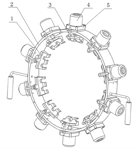
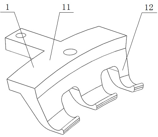
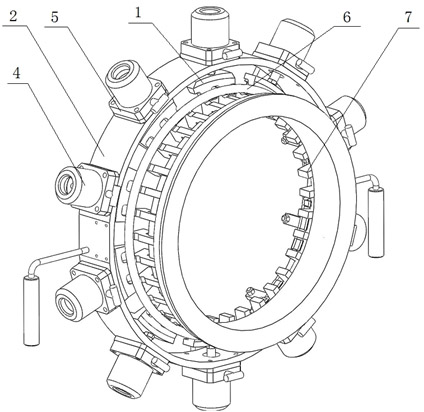
[0014] Such as Figure 1-3 As shown, a spring hoop installation tool of the present invention includes an annular bracket 2, ten cylinders 4 are evenly fixed on the outer wall of the bracket 2 along the circumferential direction of the bracket 2, and the cylinder body of the cylinder 4 communicates with the gas source through the gas circuit connecting pipe , and an air valve (not shown in the figure) for controlling the on-off of the gas-path connecting pipe is provided on the gas-path connecting pipe. The cylinder 4 includes a piston rod that expands and contracts in the radial direction of the bracket 2 and extends toward the inside of the bracket 2. The piston rod passes through the bracket 2, and the end of the piston rod is fixed on the inside of the bracket 2. Claw part 1 that pulls outward. The piston rods of the cylinders 4 drive the claws 1 to move outward along the radial direction of the bracket 2 , and at the same time, the claws 1 catch the inner ring of the spr...


PUM


Abstract

The invention discloses a fixture for installing spring band which comprises an annular bracket, wherein multiple cylinders are evenly arranged on the outer wall of the annular bracket along the circumferential direction of the bracket, each cylinder comprises a piston rod which stretches out and draws back along the radial direction of the bracket and extends to the inner side of the bracket, a claw piece which is used for hooking the inner circle of the spring band and applying radial outward tension is fixed on the tail end of the piston rod of each cylinder, which is arranged at the inner side of the bracket, and the cylinder body of each cylinder is communicated with an air source through an air channel connecting pipe. The claw pieces can be driven to move outwards along the radial direction of the bracket by the piston rods and the spring band is driven to expand outwards by the claw pieces, thus the expansion of the spring band can be easily realized, the operation is simple and the assembly efficiency is high.

Description

technical field [0001] The invention relates to a tool for installing a spring hoop on a petal-shaped contact finger of a million-volt GIS product. Background technique [0002] The petal-shaped contact finger assembly is a part used for conducting electricity in the movable part of the high-voltage circuit breaker product. It consists of 30 contact fingers evenly distributed on the outside of the cylinder, and two spring hoops are used on the outside of the contact fingers to make good contact between the contact fingers and the cylinder. . The traditional assembly is to use manpower to open the spring hoop and put it on the contact finger. Due to the large contraction force of the spring hoop, the assembly is very inconvenient. Contents of the invention [0003] The purpose of the present invention is to provide a spring hoop installation tool that can easily stretch the spring hoop, has simple operation and high assembly efficiency. [0004] The present invention adop...

Claims


Application Information

Patent Timeline
IPC IPC(8): H01H69/00
Inventor 田鹏范艳艳武松王俊
Owner PINGGAO GRP
Why Eureka
Try Eureka