Downdraft plasma garbage gasification reaction chamber and gasification process

A technology of gasification reaction chamber and plasma, which is applied in the petroleum industry and the manufacture of combustible gas, etc., can solve the problems of equipment cost increase, huge power, increase of one-time investment, etc., and achieve high operating value and reduce power consumption.

Inactive Publication Date: 2013-07-17
张建超
View PDF6 Cites 0 Cited by
  • Summary
  • Abstract
  • Description
  • Claims
  • Application Information

AI Technical Summary

Problems solved by technology

[0006] However, the current plasma garbage gasification technology still has many deficiencies. First of all, direct gasification of garbage with a plasma torch requires a huge amount of power, and its power consumption rate can reach 30% to 45% of its power generation capacity. Excessive electricity leads to greatly increased operating costs, making it unworthy of commercial operation
Second, this method gasifies garbage, and a dioxin treatment device needs to be added to the subsequent gas purification process, which increases the initial one-time investment and greatly increases the equipment cost
Third, using a plasma torch to directly gasify garbage, due to the uneven distribution of its temperature field, the garbage cannot be completely treated at high temperature, and there will be a large amount of dioxins and other harmful substances in the discharged waste residue, which makes the treatment of its waste residue become a problem. a problem

Method used


Image

  • Downdraft plasma garbage gasification reaction chamber and gasification process
  • Downdraft plasma garbage gasification reaction chamber and gasification process
  • Downdraft plasma garbage gasification reaction chamber and gasification process

Examples


Embodiment Construction

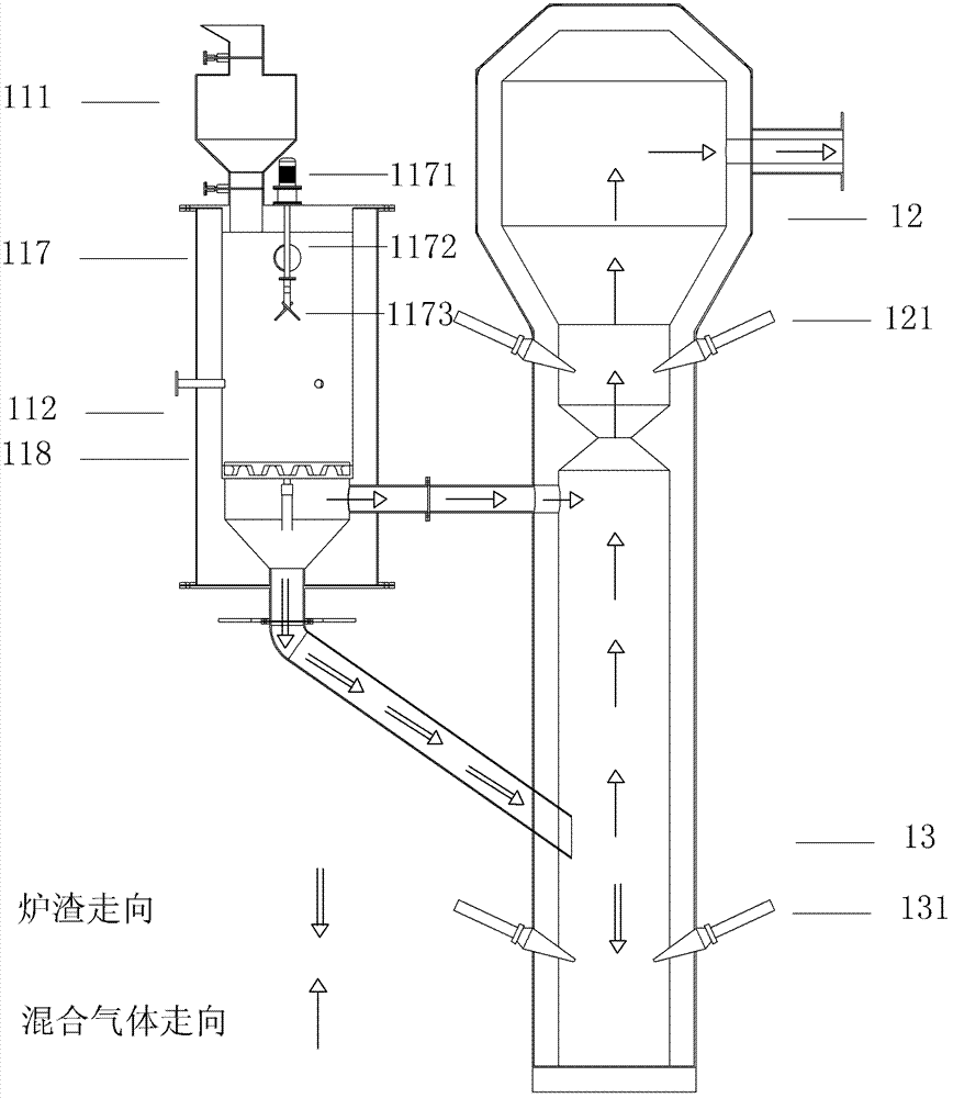
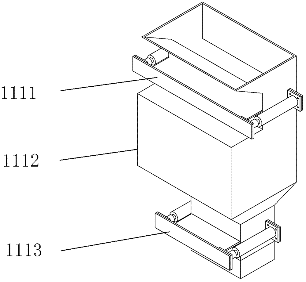
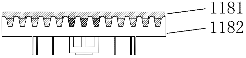
[0070] A downdraft plasma waste gasification reaction chamber, such as figure 1 As shown, it includes automatic feeding device 111, primary gasification zone 112, automatic ignition device, plasma reaction zone and furnace temperature monitoring system, furnace material level monitoring system, inlet and outlet gas temperature monitoring system, inlet and outlet pressure monitoring system and flame Monitoring System;

[0071] The material level monitoring system in the furnace is composed of two microwave material level detectors, which are installed on the top of the material layer in the primary gasification zone 3; the inlet and outlet temperature detection systems are installed at the mouth of the gas inlet delivery pipe and the outlet delivery pipe; The outlet pressure monitoring system is installed at the gas inlet and outlet pipes; the furnace temperature monitoring system includes 12 thermocouples, which are evenly distributed in the primary gasification zone.

[0072...


PUM

PropertyMeasurementUnit
thicknessaaaaaaaaaa

Abstract

The invention relates to a downdraft plasma garbage gasification reaction chamber and gasification process. The reaction chamber comprises an automatic feeding device, a primary gasification zone, an automatic ignition device, a plasma reaction zone and furnace temperature monitoring system, a furnace charge level monitoring system, an inlet / outlet gas temperature monitoring system, an inlet / outlet pressure monitoring system and a flame monitoring system; the primary gasification zone is internally provided with a vibrating grate and an automatic leveling device, and the plasma reaction zone is in an integrated structure consisting of a secondary refining zone and a gas refining zone. The process comprises the following steps of: automatic feeding; primary gasification; and plasma secondary refining and plasma gas refining. In the invention, the caloricity of garbage is utilized to generate gas, and then the generated gas and cinder are further processed by using a plasma torch, so that harmful substances in the garbage are removed, the gas yield is increased, the discharged waste residues are reduced, the disposable investment cost for garbage gasification and operation costs arereduced, and gas is cleaner.

Description

technical field [0001] The invention relates to the plasma gasification power generation technology of domestic garbage, in particular to a side-suction plasma garbage gasification reaction chamber and a gasification process thereof. Background technique [0002] The domestic waste disposal methods in my country are mainly landfill and incineration. Landfill not only occupies a large amount of land, but also pollutes groundwater, which is a last resort. Nevertheless, there are not many sites available for landfill in areas where land resources are scarce. Although the incineration method has a high volume reduction ratio and can recover energy, it has been strongly opposed by the public due to pollution problems such as dioxins. There is an urgent need to develop a new generation of alternative incineration technologies that are environmentally friendly and energy-saving. [0003] Plasma is the fourth state of matter, which has many unique physical and chemical properties ...

Claims


Application Information

Patent Timeline
Patent Type & Authority Patents(China)
IPC IPC(8): C10J3/60C10J3/66C10J3/20C10J3/30C10J3/34C10J3/84C10J3/80C10J3/72
Inventor 张建超张瑜姜晨旭唐旻张建国
Owner 张建超
Why Eureka
Try Eureka