Plasma garbage gasification device and process

A plasma and garbage technology, applied in the field of ion garbage gasification equipment and its gasification process, can solve the problems of extremely high power, no value, and increased one-time investment

Inactive Publication Date: 2012-01-25
张建超
View PDF6 Cites 21 Cited by
  • Summary
  • Abstract
  • Description
  • Claims
  • Application Information

AI Technical Summary

Problems solved by technology

[0005] However, the current plasma garbage gasification technology still has many deficiencies. First of all, direct gasification of garbage with a plasma torch requires a huge amount of power, and its power consumption rate can reach 30% to 45% of its power generation capacity. Excessive electricity leads to greatly increased operating costs, making it unworthy of commercial operation
Second, this method gasifies garbage, and a dioxin treatment device needs to be added to the subsequent gas purification process, which increases the initial one-time investment and greatly increases the equipment cost
Third, using a plasma torch to directly gasify garbage, due to the uneven distribution of its temperature field, the garbage cannot be completely treated at high temperature, and there will be a large amount of dioxins and other harmful substances in the discharged waste residue, which makes the treatment of its waste residue become a problem. a problem

Method used


Image

  • Plasma garbage gasification device and process
  • Plasma garbage gasification device and process
  • Plasma garbage gasification device and process

Examples


Embodiment 1

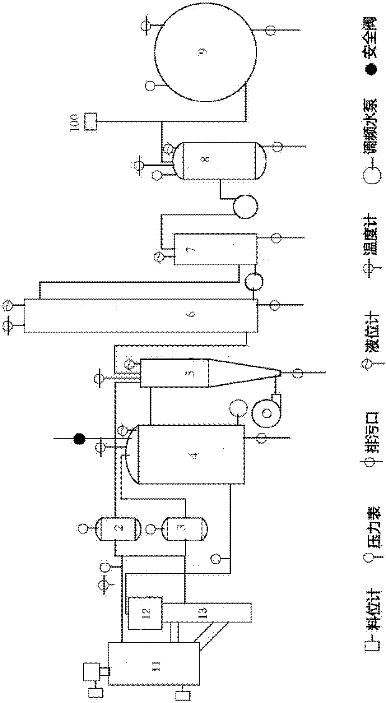
[0092] A kind of plasma garbage gasification equipment, such as figure 1 As shown, it includes a gasification reaction chamber connected by a gas pipeline, a steam heat exchanger 4 and a steam buffer tank 3, an air buffer tank 2, an internal and external double cyclone heat exchange dust collector 5, a cooling tower 6, and a hydrogen sulfide removal spray Device 7, water ring compressor, gas-water separator 8, (gas) gas storage tank 9, and the control system of equipment;

[0093] The internal and external double cyclone heat exchange dust collector 5, such as image 3 As shown, it is an integrated structure of inner and outer double-layer vertical cylinders, the upper part is cylindrical, the lower part is inverted cylindrical, the inner layer is a cyclone separation chamber 501, and the outer layer is a cyclone heat exchange chamber 502; the cyclone separation chamber 501 is divided into liquid collection area, cyclone separation area and purification area from bottom to to...

Embodiment 2

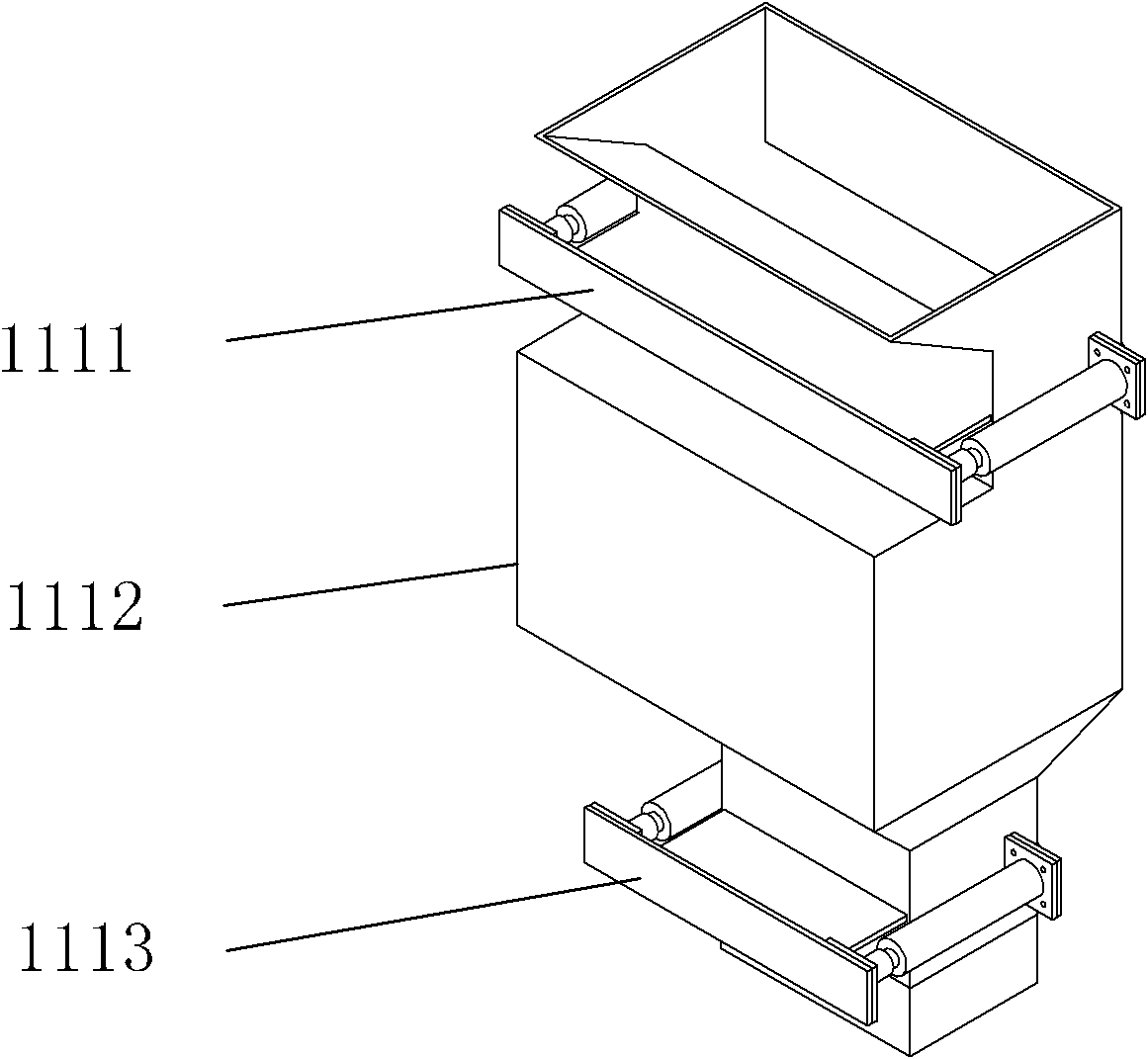
[0142] Another plasma waste gasification equipment, such as figure 1 Shown, the composition of its equipment is identical with embodiment 1, and its difference mainly lies in its gasification reaction chamber, is the downdraft plasma waste gasification reaction chamber, as Figure 5 As shown, it includes automatic feeding device 111, primary gasification zone 112, automatic ignition device, plasma reaction zone and furnace temperature monitoring system, furnace material level monitoring system, inlet and outlet gas temperature monitoring system, inlet and outlet pressure monitoring system and flame Monitoring System;

[0143] The difference from the side-suction plasma waste gasification reaction chamber described in Embodiment 1 mainly lies in:

[0144] A vibrating grate 118 and an automatic leveling device 117 are arranged in the primary gasification zone 112; the gas outlet of the primary gasification zone 112 is located below the vibrating grate 118;

[0145] The vibrati...

Embodiment 3

[0151] The third type of plasma garbage gasification equipment, such as figure 1 As shown, the composition of its equipment is the same as that of Embodiment 1, and its difference mainly lies in its gasification reaction chamber, which is a horizontal plasma garbage gasification reaction chamber, such as Figure 7 As shown, it includes automatic feeding device 111, primary gasification zone 112, automatic ignition device, plasma reaction zone and furnace temperature monitoring system, furnace material level monitoring system, inlet and outlet gas temperature monitoring system, inlet and outlet pressure monitoring system and flame Monitoring System;

[0152] The main difference from the plasma waste gasification reaction chamber described in Example 1 is that: the primary gasification zone is provided with a setback grate 115, a chain furnace adjustment 116 and an automatic leveling device 117, and the primary gasification zone 112 The air inlet is arranged between the grate 1...


PUM

PropertyMeasurementUnit
thicknessaaaaaaaaaa

Abstract

The invention relates to a plasma garbage gasification device and process. The device comprises a gasification reaction chamber, a steam heat exchanger, a steam buffer tank, an air buffer tank, an inner and outer double-cyclone heat exchanging dust collector, a cooling tower, a hydrogen sulfide removal sprayer, a water ring compressor, a gas-water separator, a gas storage tank and a control system of the device, which are connected through a gas pipeline; the gasification reaction chamber comprises an automatic feeding device, an automatic ignition device, a primary gasification zone and a plasma reaction zone; and the plasma reaction zone consists of a secondary refining zone and a gas refining zone. The process comprises the following steps of: gas generation; gasification medium preheating; gas purifying and filtering; and gas compression and storage. The invention has the characteristics of simple structural design, reasonable energy efficiency utilization, low primary input cost and low power consumption, and particularly, harmful substances such as dioxin and the like generated in the gasification process can be effectively removed, the volume reduction ratio is increased, and the waste is turned into the wealth.

Description

technical field [0001] The invention relates to the plasma gasification power generation technology of domestic garbage, in particular to a plasma garbage gasification equipment and a gasification process thereof. Background technique [0002] The domestic waste disposal methods in my country are mainly landfill and incineration. Landfill not only occupies a large amount of land, but also pollutes groundwater, which is a last resort. Nevertheless, there are not many sites available for landfill in areas where land resources are scarce. Although the incineration method has a high volume reduction ratio and can recover energy, it is strongly opposed by the public due to pollution problems such as dioxins: domestic waste and other wastes are prone to produce dioxins when the combustion temperature is lower than 300-550 °C; During the incineration of chlorine-containing plastics, the incineration temperature is lower than 800°C, and dioxins are easily generated. Dioxins are ex...

Claims


Application Information

Patent Timeline
Patent Type & Authority Applications(China)
IPC IPC(8): C10J3/60C10J3/66C10J3/20C10J3/30C10J3/34C10J3/84C10J3/80C10J3/72
CPCY02P20/10
Inventor 张建超张瑜姜晨旭唐旻张建国
Owner 张建超
Why Eureka
Try Eureka