Method for miniaturizing delay line design based on low-temperature co-firing ceramic process

A technology of low-temperature co-fired ceramics and a design method, applied in the field of radar, can solve the problems of complex realization, achieve the effect of good microwave performance and reduce the layout area

Inactive Publication Date: 2012-02-01
CHINA ELECTRONIC TECH GRP CORP NO 38 RES INST
View PDF0 Cites 7 Cited by
  • Summary
  • Abstract
  • Description
  • Claims
  • Application Information

AI Technical Summary

Problems solved by technology

[0004] There are many ways to improve the broadband performance of phased array antennas, such as equal feeder length Blass matrix, Rotman lens, etc., but on two-dimensional scanning phased array radar, these techniques are quite complicated to implement

Method used


Image

  • Method for miniaturizing delay line design based on low-temperature co-firing ceramic process
  • Method for miniaturizing delay line design based on low-temperature co-firing ceramic process
  • Method for miniaturizing delay line design based on low-temperature co-firing ceramic process

Examples


example

[0035] Typical example: Design an X-band miniaturized 5-bit delay line

[0036] A certain system works in the X-band, and its sub-array stage needs delay lines with a maximum of 31 wavelengths for delay compensation. According to the layout requirements of the antenna array structure, the overall size of the delay amplification component shall not exceed 80mm×45mm×10mm, and the weight No more than 90 grams.

[0037] According to the above design requirements, applying the technology of the present invention, the delay line design process in the delay amplifier assembly is as follows:

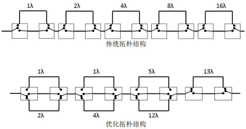
[0038] 1) The maximum delay of 31 wavelengths corresponds to a 5-bit delay, and the delay line topology optimization method is applied. The 5-bit delay line topology can use 3 pairs of single-pole three-throw switches plus a pair of single-pole double-throw switches To achieve, a pair of switches is reduced compared with the traditional form. In the optimized topology, there can be many differen...


PUM


Abstract

The invention discloses a method for miniaturizing a delay time design by adopting a low-temperature co-firing ceramic process. By using the method, the difficult problems that the volume size is difficult to decrease in a conventional delay line design, the performance of a delay line is influenced by the resonance oscillation of a cavity more greatly, the chromatic dispersion phenomenon is caused by the intercoupling between the delay lines, and the like, are solved. In a routine delay line design adopting a way of a switch as well as a transmission line, the transmission line generally adopts the way of a plane microstrip line which is easy to process, but due to the semi-open field distribution of the microstrip line, the microstrip line can be caused to be easily influenced by the resonance oscillation of the cavity of the transmission line, further, the intercoupling is serious when the compact wiring is carried out between transmission lines, and the more obvious chromatic dispersion characteristic is caused. According to the method, a strip line which is not easy to influence is used as a main way of a delay transmission line; the topological structure of the delay line is optimized; by adopting a microwave multilayer circuit design technique, a switch control circuit and a microwave delay circuit are comprehensively designed on a low-temperature co-fired ceramic baseplate; the layout area of the circuits is greatly reduced; and the circuits also have better microwave performance synchronously.

Description

technical field [0001] The invention belongs to the technical field of radar, and in particular relates to a design method of a miniaturized delay line based on a low-temperature co-fired ceramic process. [0002] The invention can be used in the time-delay amplifying component of the active phased array radar, and can be applied to various types of military or civilian radars adopting the active phase-scanning system. Background technique [0003] In the phased array antenna, the radiated energy of the antenna radiating elements is added in phase in space to generate the array focus, thereby forming the antenna beam. When the beam pointing perpendicular to the array aperture direction, each antenna unit is in-phase radiation, when the frequency changes, the phase states of all units change synchronously, and still maintain the same phase relationship, so the antenna beam pointing has nothing to do with frequency; when the beam pointing is When other angles are not perpendi...

Claims


Application Information

Patent Timeline
Patent Type & Authority Applications(China)
IPC IPC(8): H01P11/00H01P9/00
Inventor 吕春明戴跃飞刘海明杜丽军王光池
Owner CHINA ELECTRONIC TECH GRP CORP NO 38 RES INST
Why Eureka
Try Eureka