Painting apparatus

A paint and container technology, applied in the field of application equipment, can solve the problems of wasting time and high risk of paint splashing

Inactive Publication Date: 2013-10-09
AKZO NOBEL COATINGS INT BV
View PDF1 Cites 0 Cited by
  • Summary
  • Abstract
  • Description
  • Claims
  • Application Information

AI Technical Summary

Problems solved by technology

Users find this known process a waste of time due to having to continually dip paint from the roller pan onto the roller and pour paint from the paint container into the roller pan
There is a high risk of splashing the paint due to the need to pour the paint into the roller pan and then dip the paint onto the roller before applying the paint to the surface

Method used


Image

  • Painting apparatus
  • Painting apparatus
  • Painting apparatus

Examples


Embodiment Construction

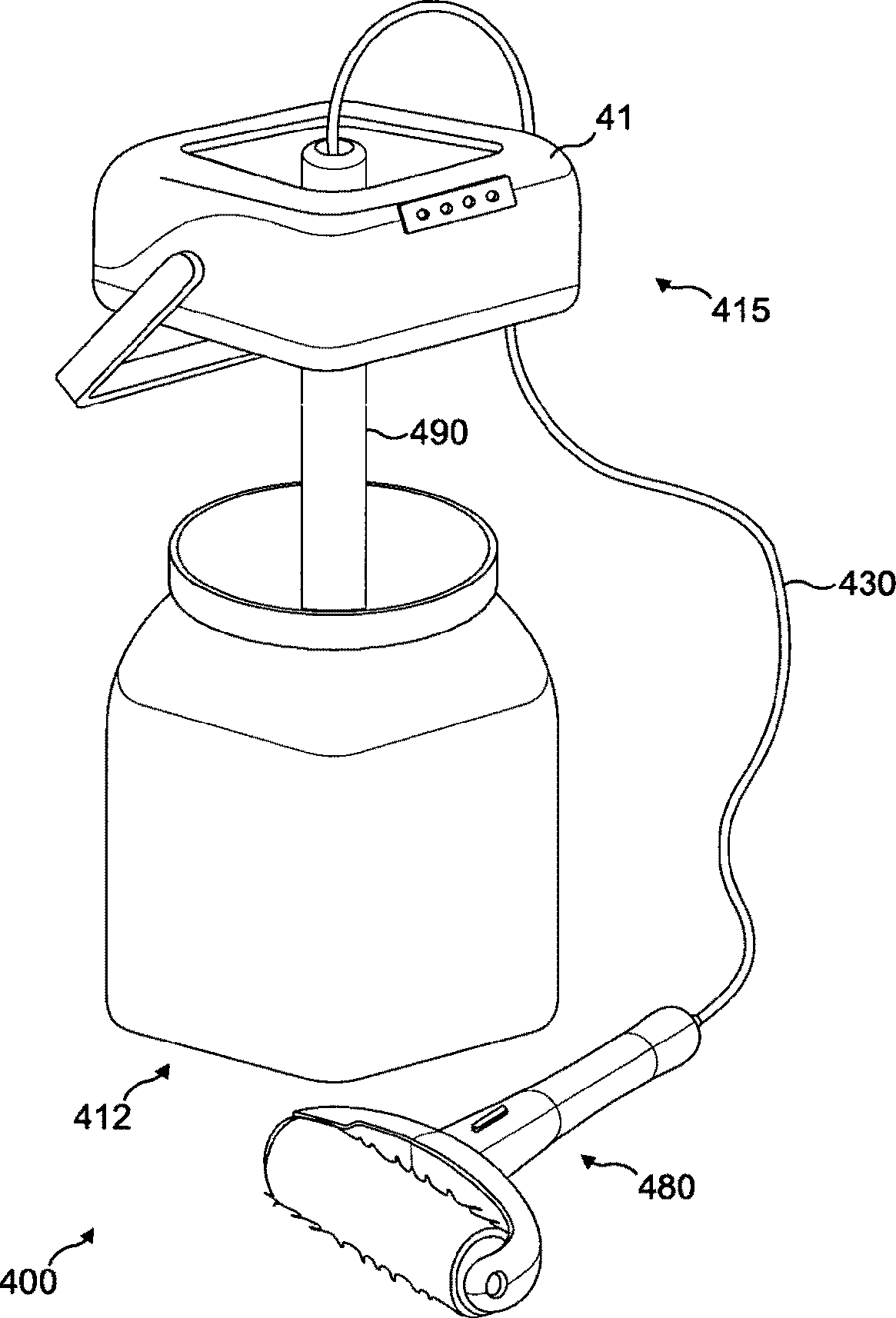
[0017] figure 1 A prior art applicator device 400 is shown including a paint container 412 , closure module 415 , dip tube assembly 490 and roller assembly 480 . The dip tube assembly is fluidly connected to the roller assembly 480 through a conduit 430 . Such a device is described in GB2448578.

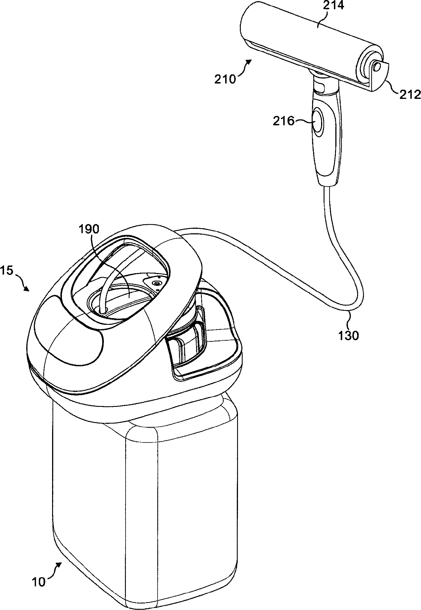
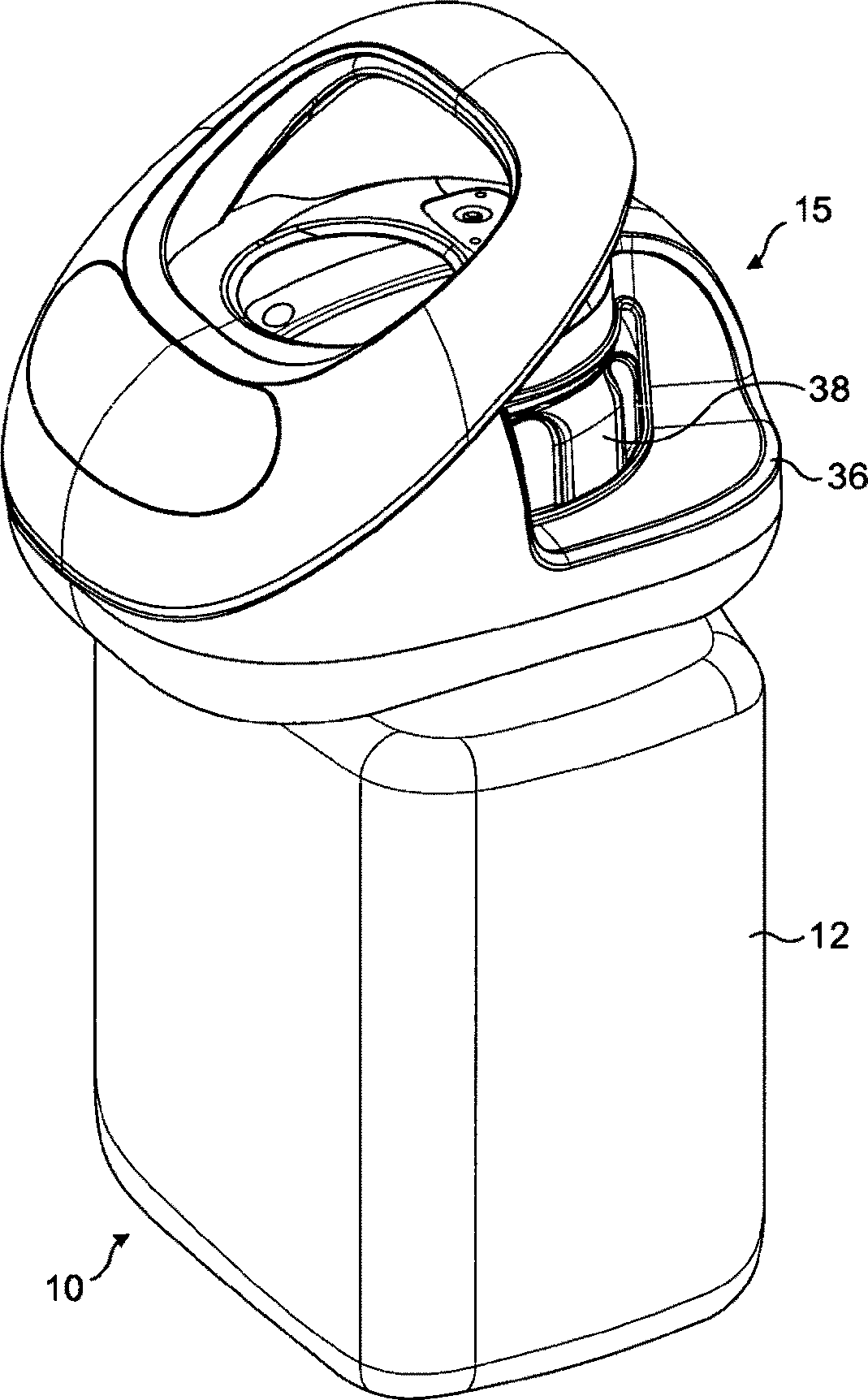
[0018] refer to Figures 2 to 22 , which show the application device 10 of the present invention, which includes a paint container 12 , a closure module 15 , a dip tube assembly 190 and a roller assembly 210 . Dip tube assembly 190 is fluidly connected to roller assembly 210 through conduit 130 .

[0019] The roller assembly 210 includes a roller cage 212 containing a roller 214 and a switch 216 .

[0020] The paint container 12 includes a body 14 , a collar 16 , a handle 18 and a removable closure 20 . The body 14 has an inwardly tapering neck portion 22 and an upstanding rim portion 24 . Upstanding rim portion 24 has a rim 25 defining a container aperture 26 ( Figure 4 and ...


PUM


Abstract

A painting apparatus comprising a paint container and a closure module, the paint container having a screw threaded rim, the closure module having a main housing and an outer ring, the outer ring having a screw thread, in which the outer ring is rotatable relative to the main housing such that the screw thread cooperates with the threaded rim of the paint container to secure the closure module onto the paint container without having to rotate the main housing relative to the paint container.

Description

technical field [0001] The invention relates to an applicator. Background technique [0002] It is known for users to pour paint from a paint container into a roller pan, use the roller pan to dip the paint onto the roller, and then use the roller to apply the paint to a surface such as a wall or ceiling. Users find this known procedure a waste of time due to having to continually dip paint from the roller pan onto the roller and pour paint from the paint container into the roller pan. Due to the need to pour the paint into the roller pan and then dip the paint onto the roller before applying the paint to the surface, there is a high risk of spilling the paint. [0003] There are application devices that automatically feed paint from a paint container to a roller without pouring paint into the roller pan and dipping the paint onto the roller. The applicant's co-pending patent application GB2448578 describes an application device comprising a roller assembly and a closure m...

Claims


Application Information

Patent Timeline
Patent Type & Authority Patents(China)
IPC IPC(8): B05C17/00B65B31/00B44D3/12B65D45/30
CPCB05C17/0333B44D3/127B65D41/0442B65D45/305
Inventor C·J·奥德
Owner AKZO NOBEL COATINGS INT BV
Why Eureka
Try Eureka