U-shaped pipe mould device

A U-shaped tube and mold technology, which is applied in the field of U-shaped tube mold devices, can solve problems such as the inability to install cooling channels in the mold core device, damage to the U-shaped tube, and high core-pulling force, and achieve small core-pulling force and reliable performance , The effect of easy core pulling

Active Publication Date: 2013-11-20
厦门华盛弘精密模具有限公司
View PDF6 Cites 0 Cited by
  • Summary
  • Abstract
  • Description
  • Claims
  • Application Information

AI Technical Summary

Problems solved by technology

Although this method can solve the core-pulling problem, it also has the following disadvantages: 1. It is impossible to install a cooling water channel in the mold core device; 2. The core-pulling force is extremely large, but if it is too large, it will cause damage to the U-shaped tube, so the waste product high rate

Method used


Image

  • U-shaped pipe mould device
  • U-shaped pipe mould device
  • U-shaped pipe mould device

Examples


Embodiment Construction

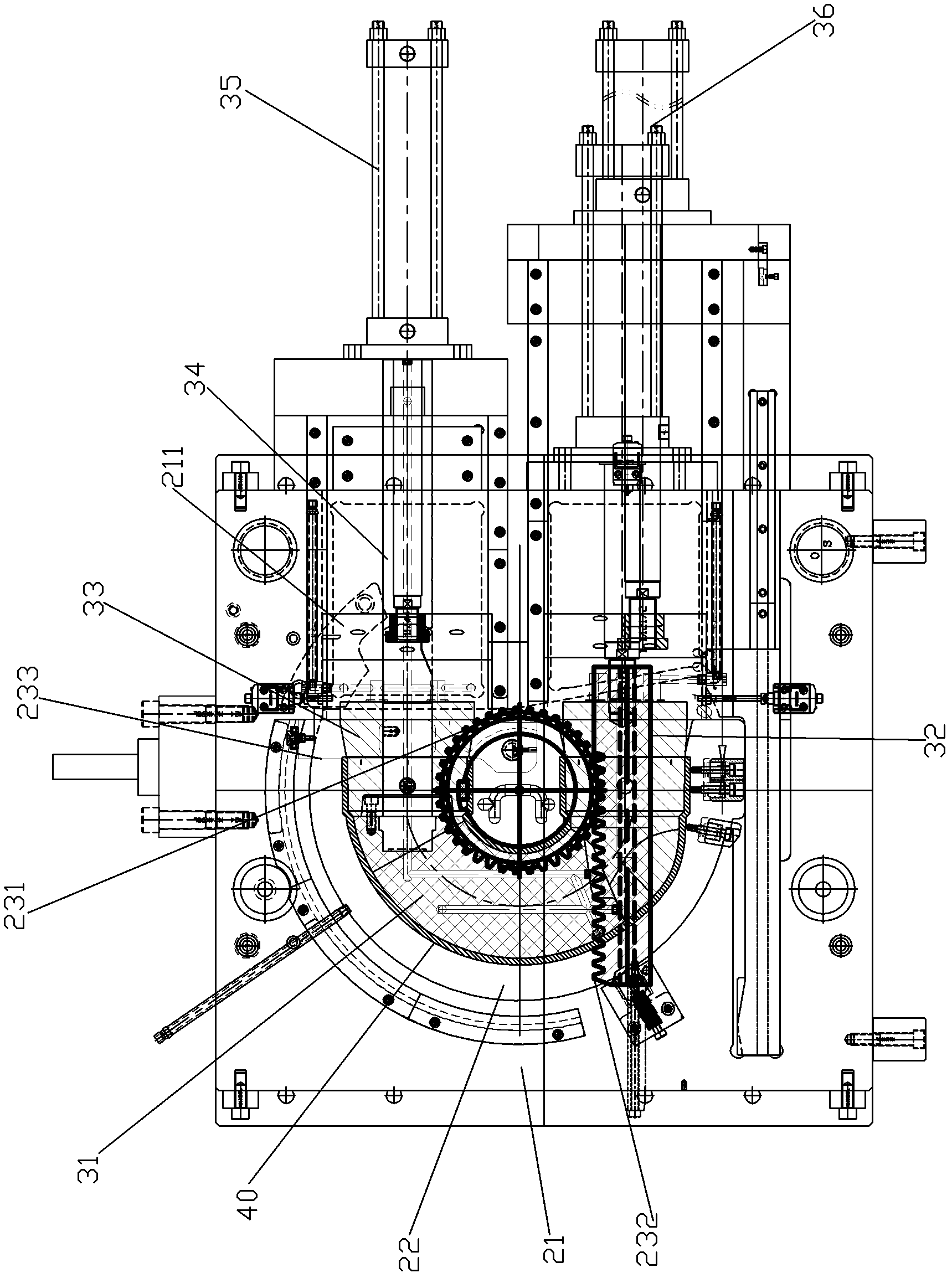
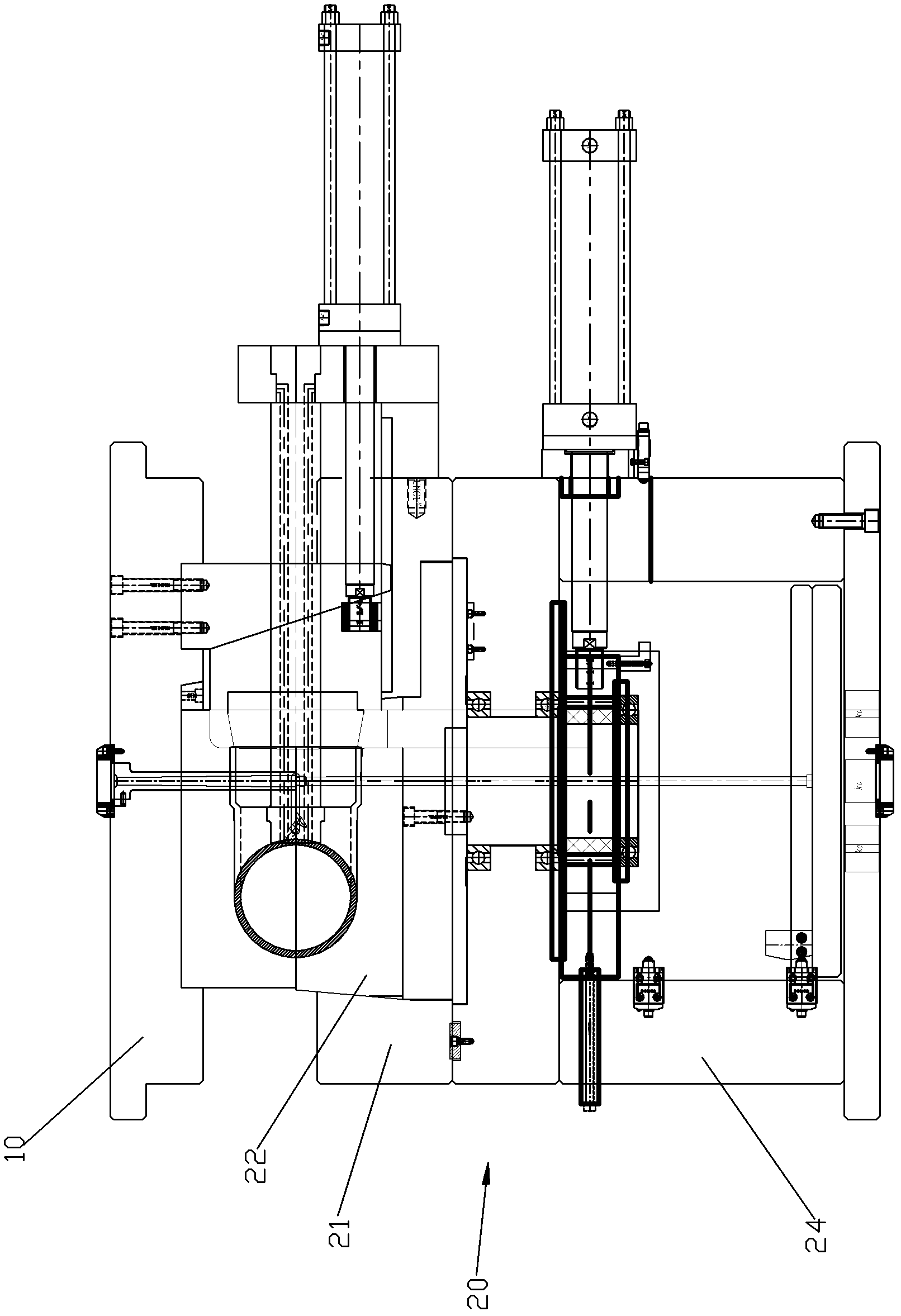
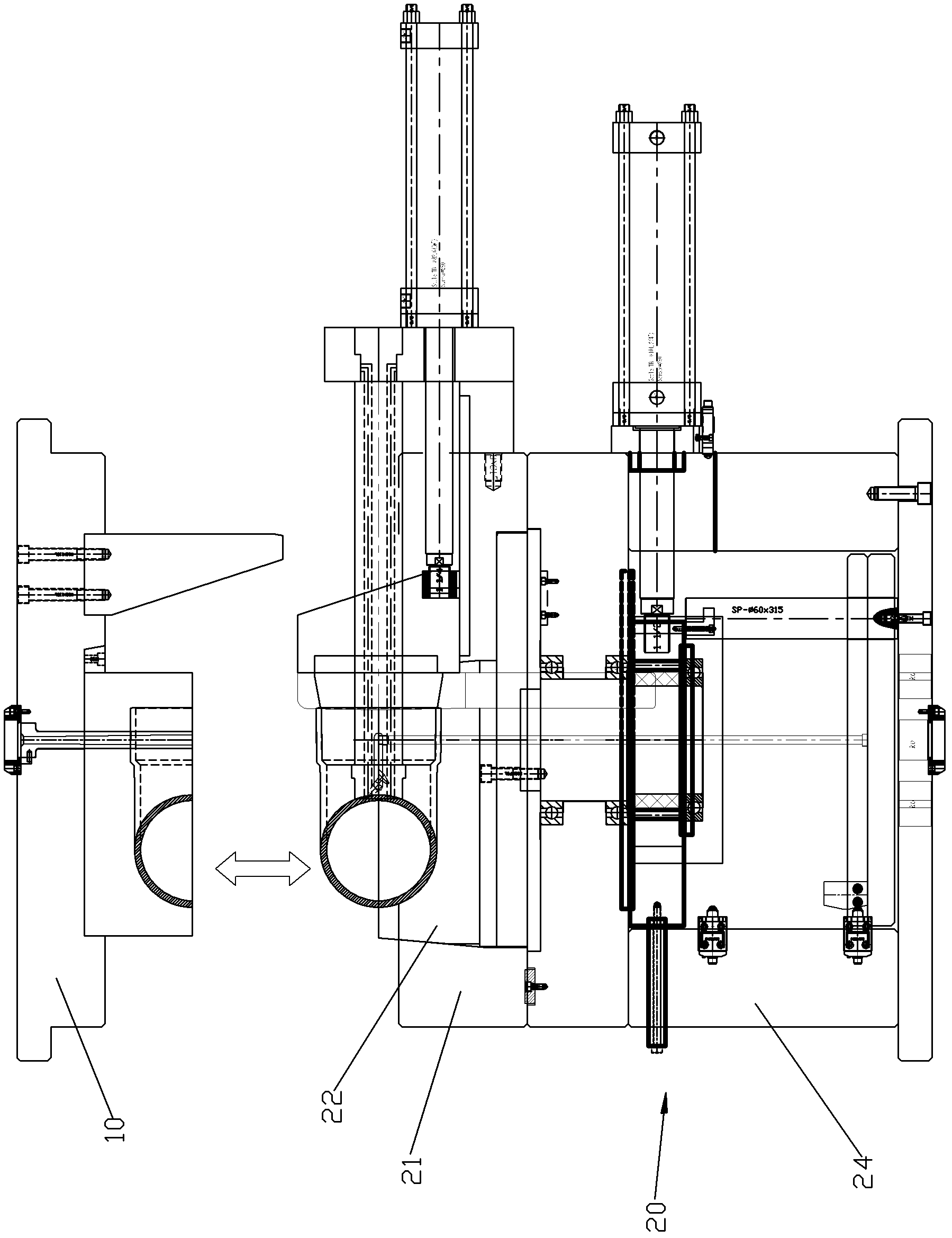
[0028] Please check Figure 1 to Figure 7 , U-shaped pipe mold device, which includes a mold and a core device installed in the mold, which is used to form U-shaped pipe 40.

[0029] The mold includes an upper template 10 and a lower template unit 20, and an up and down pushing mechanism is set between the upper template and the lower template unit. The upper formwork 10 and the lower formwork unit 20 cooperate to form a mold cavity adapted to the U-shaped pipe. The upper template 10 is provided with a downward upper half cavity. The lower template unit 20 includes a lower template 21, a U-shaped outer template 22 rotatably connected to the lower template 21, a transmission unit and a first drive unit. The outer template 22 is provided with an upwardly facing lower half cavity, and the upper half cavity and the lower half cavity cooperate to form a mold cavity. The first drive unit is connected to the outer formwork 22 to drive the outer formwork 22 to rotate relative to th...


PUM


Abstract

The invention discloses a U-shaped pipe mould device. A mould comprises an upper mould plate and a lower mould plate unit. A downward upper half cavity is arranged below the upper mould plate, the lower mould plate unit comprises a lower mould plate, a U-shaped outer mould plate, a transmission unit and a driving unit, the U-shaped outer mould plate is rotatably connected onto the lower mould plate, the outer mould plate is provided with an upward lower half cavity, and the driving unit is connected with the outer mould plate to drive the outer mould plate to rotate relative to the lower mould plate. A mould core device comprises an arc section, a left section, a right section and a positioning column, wherein the arc section, the left section and the right section are abutted and are matched with an inner cavity of a U-shaped pipe, the positioning column is connected to the lower mould plate in a positioned manner, the tail end of the positioning column is connected to the right end of the arc section in a positioned manner, the right section is sleeved outside the positioning column and is capable of moving along the positioning column, and the left section is slidably connected with the lower mould plate. In addition, another driving unit is in transmission connection with the left section, and the transmission unit is in transmission connection with the second driving unit, so that the second driving unit can drive the outer mould plate to swing relative to the lower mould plate through the transmission unit to shift the U-shaped pipe and the arc section to relatively move and to release connecting force between the U-shaped pipe and the arc section.

Description

technical field [0001] The present invention relates to a U-shaped tube mold assembly. Background technique [0002] Existing U-shaped pipe mold device, it comprises a mold and a core device installed in the mould, said mold includes an upper template and a lower template unit, the upper template and the lower template unit cooperate to form a suitable U-shaped The mold cavity of the pipe, the existing core device mostly adopts a serial connection to connect a plurality of snake sections, and every two snake sections are hinged. Although this method can solve the core-pulling problem, it also has the following disadvantages: 1. It is impossible to install a cooling water channel in the mold core device; 2. The core-pulling force is extremely large, but if it is too large, it will cause damage to the U-shaped tube, so the waste product The rate is high. Contents of the invention [0003] The invention provides a U-shaped pipe mold device, which overcomes the shortcomings ...

Claims


Application Information

Patent Timeline
Patent Type & Authority Patents(China)
IPC IPC(8): B29C33/04B29C33/44B29C33/76
Inventor 郑佳勇
Owner 厦门华盛弘精密模具有限公司
Why Eureka
Try Eureka