Flexible demolding device

A flexible and demolding technology, applied in the field of injection mold equipment, can solve the problems of cumbersome demolding process, long molding cycle, low production efficiency, etc., to reduce demolding time, reduce friction and improve work efficiency.

Active Publication Date: 2022-05-27
XIAMEN UNIV OF TECH
View PDF11 Cites 0 Cited by
  • Summary
  • Abstract
  • Description
  • Claims
  • Application Information

AI Technical Summary

Problems solved by technology

In injection molding, the demoulding process of the core is cumbersome, and the demoulding process takes up a lot of time, resulting in a longer molding cycle of the product and lower production efficiency of the enterprise. If the demoulding time in injection molding is reduced, it can be Greatly improve its production efficiency

Method used


Image

  • Flexible demolding device
  • Flexible demolding device
  • Flexible demolding device

Examples


Embodiment 1

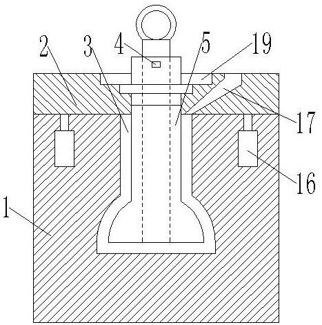
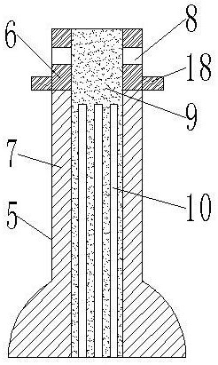
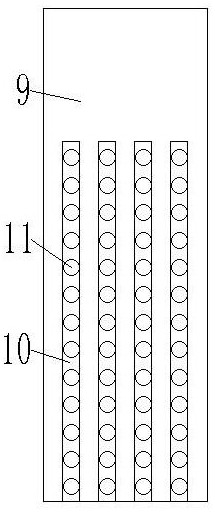
[0045] like Figure 1-5 As shown, a flexible demoulding device includes a concave mold 1 and a convex mold 2, the concave mold 1 is arranged corresponding to the convex mold 2, the convex mold 2 is provided with an injection port 17, and the concave mold 1 is provided with a The cavity 3, the injection port 17 communicates with the inner side of the cavity 3, the punch 2 is provided with a core 5, the core 5 is located inside the cavity 3, and the core 5 is used with the cavity 3 In order to form plastic products, the core 5 is provided with a through hole, and a metal core 9 is arranged in the through hole. During the injection molding process, the metal core 9 is used to provide a supporting force to make the core 5 . Keeping a certain shape and not easily deformed, a gap is set between the metal core 9 and the inner wall of the core 5, and a plurality of miniature steel balls 11 are arranged in the gap. The filling and pressure holding stages can ensure the dimensional acc...

Embodiment 2

[0051] Combined with Example 1 and Figure 5 As shown, the trajectory cosine function curve of the channel 10, the channel 10 is uniformly arranged on the surface of the metal core 9, and the trajectory of the channel 10 is set as a cosine function curve, which extends the movement distance of the miniature steel ball 11 during core pulling, The interference friction between the adjacent miniature steel balls 11 is avoided, and the metal core 9 can be pulled out smoothly. The cosine function of the channel trajectory is y=a·cosα, where a is the correlation coefficient. The diameter of the core 5 is R, and the diameter of the through hole on the core 5 is r, then a=β·r / R, where β is the correction coefficient, the value range is 0.89-0.93, when the value of β When the range is less than 0.89, the curvature of the channel track is small. When the metal core 9 is drawn out, the micro steel balls 11 are prone to sliding, and friction occurs between the micro steel balls 11, which...

Embodiment 3

[0054] In combination with the second embodiment, the cosine function of the channel trajectory is y=a·cosα, which can be further described as y=β·r / R·cosα, where β is a correction coefficient, and the value range is 0.89-0.97, and R is taken as 20mm, r is 10mm, carry out the insertion and extraction experiment of the metal core 9, and test the smoothness of the insertion and extraction process. In order to simplify the experiment, measure the change curve of the force used in the process of inserting and pulling out the metal core 9, and the change curve of the force fluctuates. When it is larger, it means that when the metal core is pulled out, there is interference between the internal micro steel balls, which affects the movement of the micro steel balls. Collect the data of the force change curve, collect 10 groups of its smaller values, take the average a1, collect 10 groups of its larger values, take the average value a2, and use k=a1 / a2 to represent the change of force,...


PUM


Abstract

The flexible demolding device comprises a female mold and a male mold, the female mold and the male mold are correspondingly arranged, the male mold is provided with an injection molding opening, a concave cavity is formed in the female mold, the injection molding opening is communicated with the inner side of the concave cavity, a mold core is arranged on the male mold and located on the inner side of the concave cavity, a through hole is formed in the mold core, and the through hole is communicated with the injection molding opening. A through hole is formed in the female die, a metal mold core is arranged in the through hole, a gap is formed between the metal mold core and the inner wall of the mold core, a plurality of miniature steel balls are arranged in the gap, a plurality of telescopic pieces are arranged in the female die, and output shafts of the telescopic pieces make contact with the male die. And the mold core is arranged and is made of a flexible material, so that quick core pulling can be carried out after injection molding is finished, the demolding time is greatly shortened, and the demolding working efficiency is improved.

Description

technical field [0001] The invention belongs to the technical field of injection mold equipment, and in particular relates to a flexible demoulding device. Background technique [0002] Injection molding is a method for the production and modeling of industrial products. In the injection mold industry, the molding of hollow circular or arc-shaped composite parts generally uses blow molding and rotational molding. In injection molding, the demolding process of the core is cumbersome, and the demolding process takes up a lot of time, resulting in a long molding cycle of the product and low production efficiency of the enterprise. If the demolding time in injection molding is reduced, it can be Greatly improve its production efficiency. SUMMARY OF THE INVENTION [0003] Aiming at the deficiencies of the prior art, the purpose of the present invention is to provide a flexible demoulding device. By setting a core, the core is a flexible material, and the core can be pulled qui...

Claims


Application Information

Patent Timeline
Patent Type & Authority Applications(China)
IPC IPC(8): B29C45/73B29C45/44B29C45/26B29C45/36B29C33/76
CPCB29C45/7337B29C45/4421B29C45/26B29C45/36B29C33/76
Inventor 葛晓宏吕福恒张志文朱秋华李辉王金伙朱一梁
Owner XIAMEN UNIV OF TECH
Why Eureka
Try Eureka