Collet chuck

A chuck chuck and chuck technology, which is applied to chucks, accessories of tool holders, pipes/pipe joints/pipes, etc., can solve the problems of expensive production and assembly, complex structure of chuck chucks, etc., and achieve uniformity. Force action, the effect of promoting alignment

Inactive Publication Date: 2012-09-05
ROHM CO LTD
View PDF9 Cites 5 Cited by
  • Summary
  • Abstract
  • Description
  • Claims
  • Application Information

AI Technical Summary

Problems solved by technology

The collet chuck has a complex construction with several components necessary for hydraulic adjustment, so that the resulting production and assembly are relatively expensive

Method used


Image

  • Collet chuck
  • Collet chuck
  • Collet chuck

Examples


Embodiment Construction

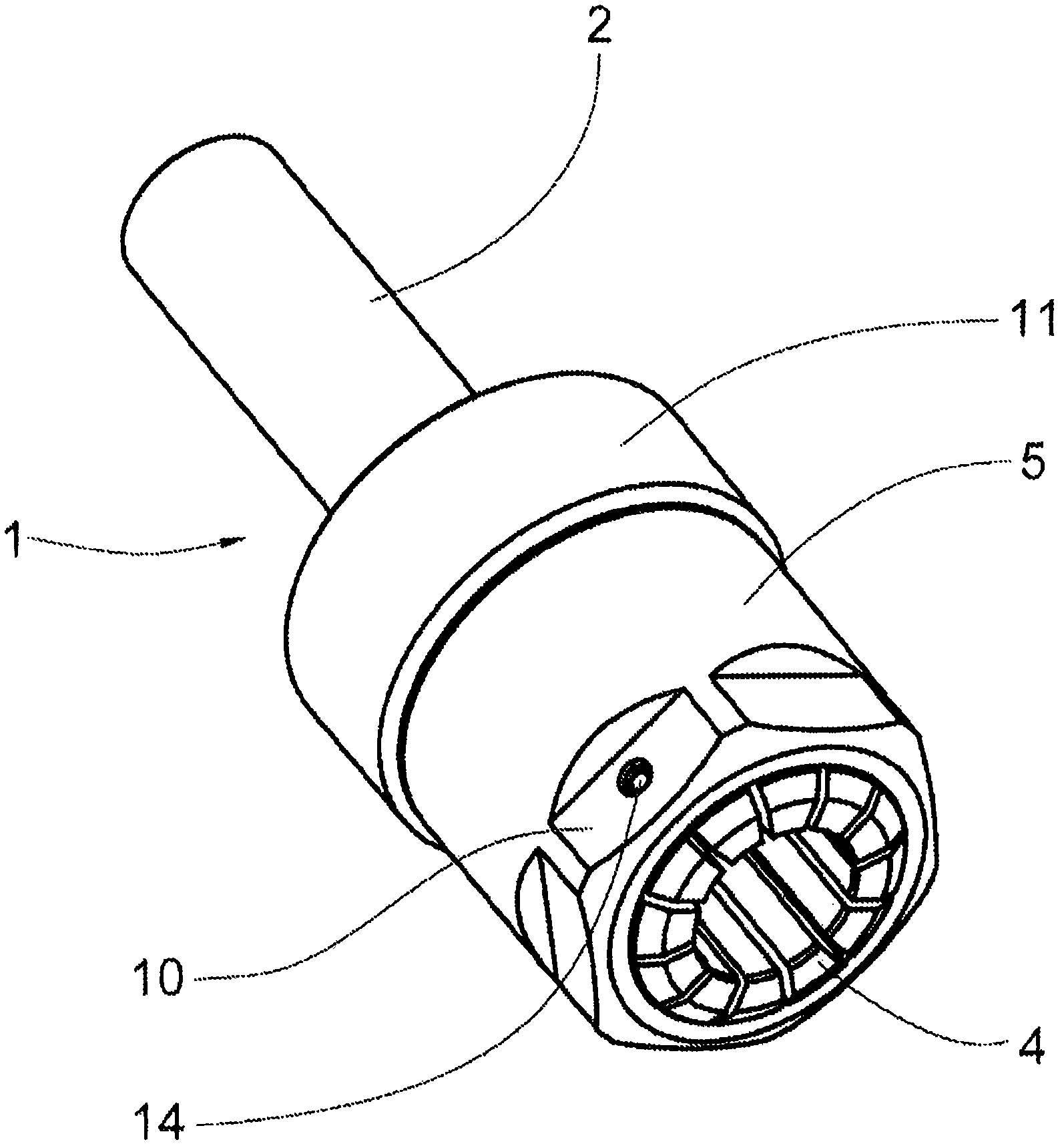
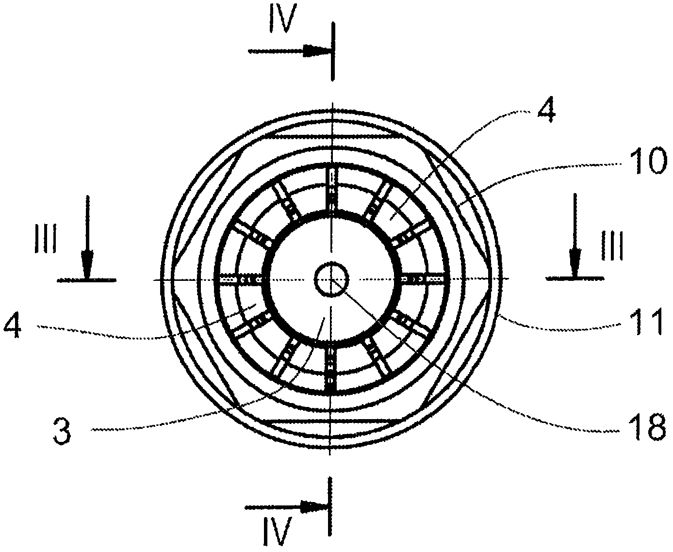
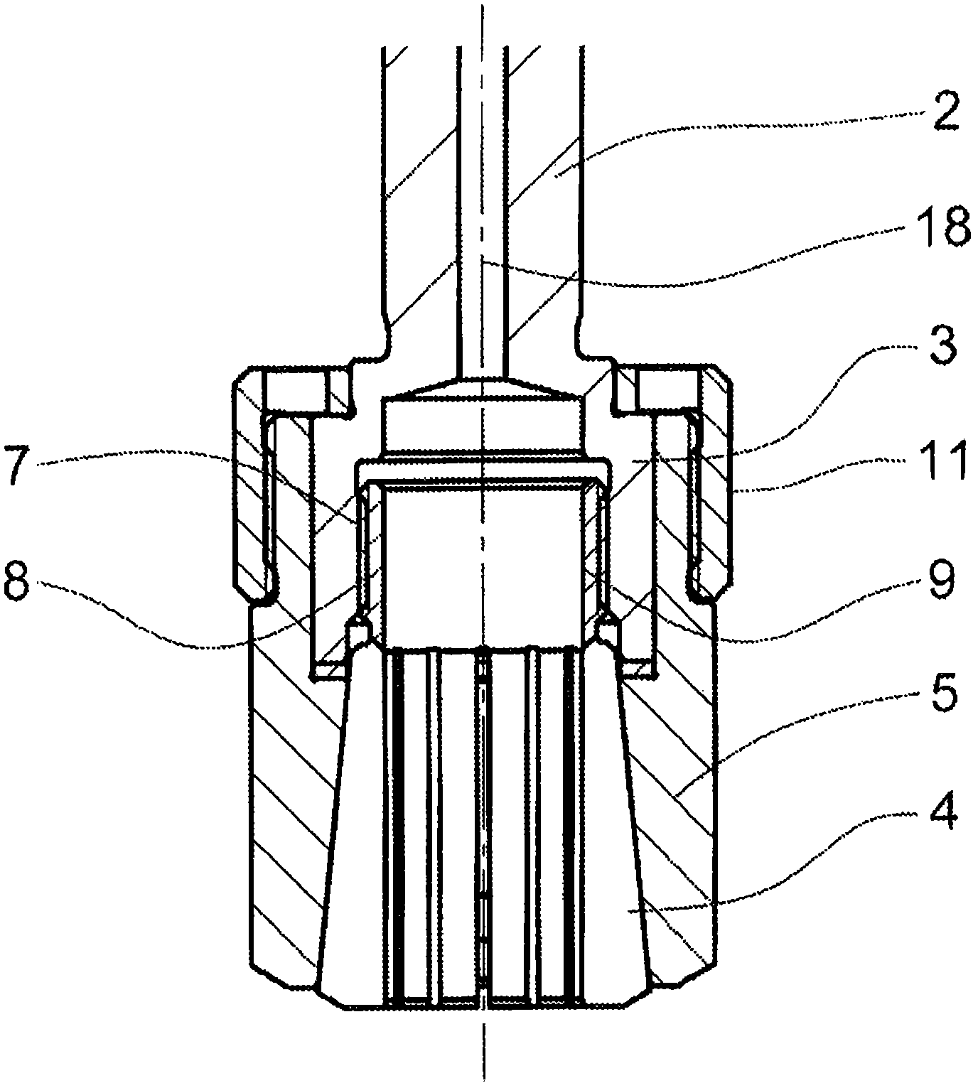
[0032] in the attached Figure 1 to Figure 15 Shown in the collet chuck 1, what is common to them is that it has a chuck body 3 connected or connectable to the drive shaft 2 in a rotationally fixed manner, a collet 4 and a cone associated with the chuck body 3 shaped sleeve 5. The conical sleeve 5 itself is arranged axially immovably on the chuck body 3 . In addition, a threaded connection 6 is effective between the chuck body 3 and the collet 4, so that when the axis of the workpiece or tool (for example an upper milling cutter) is clamped, the basic clamping is achieved by the rotation of the chuck body 3 (Grundspannung ). In operation of the collet chuck 1, a braking torque acts on the tool, which is a torque opposite to the direction of rotation of the drive shaft 2, so that a rotation of the collet 4 relative to the chuck body 3 is achieved, which due to The formed screw connection 6 brings about an axial displacement of the collet 4 . This axial movement of the colle...


PUM


Abstract

The invention relates to a collet chuck (1), comprising a chuck body (3) that is or can be connected in a rotationally fixed manner to a drive spindle (2), a collet (4), and a conical sleeve (5) associated with the chuck body (3). The conical sleeve (5) is arranged on the chuck body (3) in such a way that the conical sleeve cannot slide axially, and a threaded connection (6) is effective between the chuck body (3) and the collet (4).

Description

technical field [0001] The invention relates to a collet chuck (Spannzangenfutter) with a chuck body connected or connectable to a drive shaft in a rotationally fixed manner, with a collet (Spannzange) and a cone associated with the chuck body Socket (Konushuelse). Background technique [0002] Such a collet chuck is known from document EP 2 008 748 A2, in which the collet is in a conical sleeve and it is accommodated in the chuck body such that the lock nut is screwed onto the collet On the external thread at the disc body, so that the first clamping can be achieved by tightening the lock nut, which can rotate relative to the collet. Another clamping is then achieved in that the conical sleeve is displaced in the axial direction by a hydraulic clamping system embodied in the chuck body. The collet chuck has a complex construction with a plurality of components necessary for hydraulic adjustment, so that the resulting production and assembly are relatively expensive. Con...

Claims


Application Information

Patent Timeline
Patent Type & Authority Applications(China)
IPC IPC(8): B23B31/20
CPCY10T279/17538B23B31/20125
Inventor H-D·马克
Owner ROHM CO LTD
Why Eureka
Try Eureka