Pavement milling machine and landing leg swinging mechanism thereof

A swing mechanism and milling machine technology, applied in the field of construction machinery, can solve the problems of increasing cost, reserving a large space, increasing operation steps, etc., and achieve the effect of occupying less space and compact structure

Inactive Publication Date: 2014-04-16
SANY HEAVY IND CO LTD (CN)
View PDF3 Cites 0 Cited by
  • Summary
  • Abstract
  • Description
  • Claims
  • Application Information

AI Technical Summary

Problems solved by technology

At present, the general-purpose devices for swinging outriggers are implemented by rotating around a fixed axis. This way of swinging outriggers will cause a 180° change in the forward direction of the tires or crawlers connected to the outriggers. Therefore, it is necessary to increase the direction of rotation. Valves are used to switch the direction of the oil circuit to change the forward direction of the tire or track, which not only increases the cost but also increases the operation steps, which is not convenient for users to use
In addition, the swing leg device of some milling machines adopts a parallelogram four-bar linkage mechanism to fix the leg on the connecting rod parallel to the frame. This structure does not change the tire or track when swinging the leg. forward direction, but the swing device has a large swing range, and a large space needs to be reserved

Method used


Image

  • Pavement milling machine and landing leg swinging mechanism thereof
  • Pavement milling machine and landing leg swinging mechanism thereof
  • Pavement milling machine and landing leg swinging mechanism thereof

Examples


Embodiment Construction

[0029] The following will clearly and completely describe the technical solutions in the embodiments of the present invention with reference to the accompanying drawings in the embodiments of the present invention. Obviously, the described embodiments are only some, not all, embodiments of the present invention. Based on the embodiments of the present invention, all other embodiments obtained by persons of ordinary skill in the art without making creative efforts belong to the protection scope of the present invention.

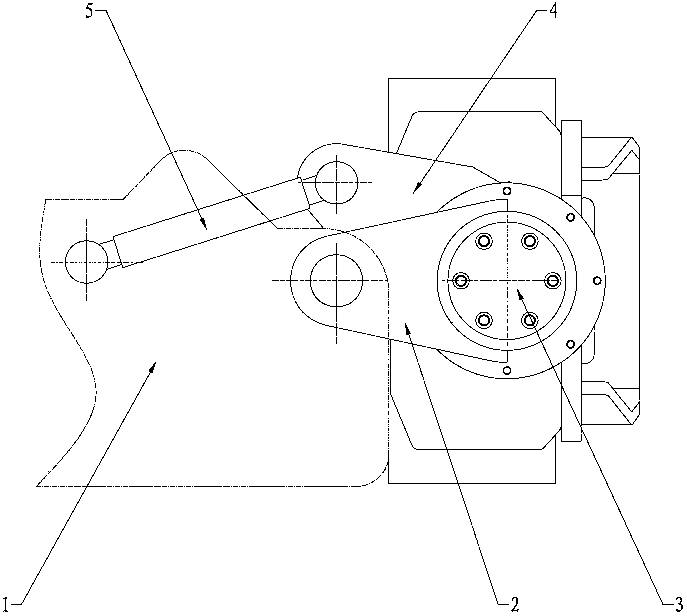
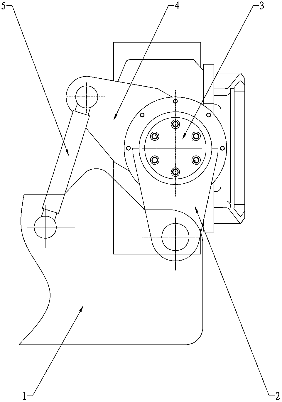
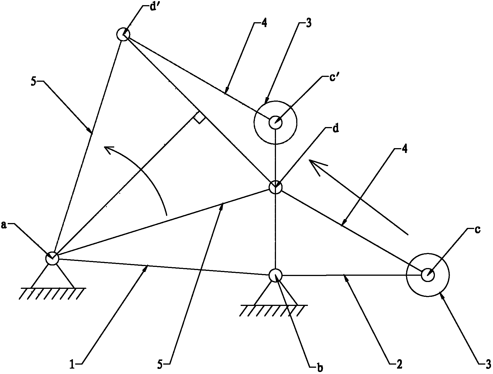
[0030] Figure 1 to Figure 5 It is the related accompanying drawing of preferred embodiment of the present invention, such as Figure 1 to Figure 5 As shown, the leg swing mechanism of the road milling machine described in this embodiment includes a hinged four-bar mechanism composed of a frame 1, a swing rod 5, a rotatable sleeve rod 2 and a fixed connecting rod 4. Among them, the hinged four-bar mechanism is a double rocker mechanism in which the fixed conn...


PUM


Abstract

A road milling machine and a leg swinging mechanism for same. The leg swinging mechanism comprises a dual-rocker mechanism formed of a frame (1), a swing rod (5), a rotatable sleeve rod (2), and a fixed connecting rod (4). The swing rod (5) and the rotatable sleeve rod (2) are rockers. The fixed connecting rod (4) is a connecting rod. A rotatable connection is formed between the fixed connecting rod (4) and the rotatable sleeve rod (2) with a leg (3) of the road milling machine being a hinge axis, and the fixed connecting rod (4) and the leg (3) are fixedly connected, and are parallel to each other before and after the swinging of the dual-rocker mechanism. The structure of the leg swinging mechanism does not change the travel direction of the tires or continuous tracks during the swinging of the leg (3), and with small movement ranges of the two rockers, the leg (3) located at the hinge point has a large displacement range, is compact in structure, and occupies a small space.

Description

technical field [0001] The invention relates to the field of engineering machinery, in particular to a road milling machine and a leg swing mechanism thereof. Background technique [0002] Road milling machine is one of the main types of road maintenance machinery, which is widely used in urban municipal road and highway maintenance projects. When the road surface milling machine is milling the edge of the road surface, one side of the outrigger needs to be swung to the inside of the milling machine, so that the milling device can successfully complete the milling of the road edge. At present, the general-purpose devices for swinging outriggers are implemented by rotating around a fixed axis. This way of swinging outriggers will cause a 180° change in the forward direction of the tires or crawlers connected to the outriggers. Therefore, it is necessary to increase the direction of rotation. Valves are used to switch the direction of the oil circuit to change the forward dir...

Claims


Application Information

Patent Timeline
Patent Type & Authority Patents(China)
IPC IPC(8): E01C23/088
CPCE01C23/12E01C23/088
Inventor 元小强刘川延伟
Owner SANY HEAVY IND CO LTD (CN)
Why Eureka
Try Eureka