A bionic flapping-wing micro-aircraft based on the change of the center of gravity of the two-wing differential and the steering gear to achieve high control torque

A micro-aircraft and torque control technology, applied in the field of bionic flapping-wing micro-aircraft, can solve the problems of small control torque, limited range of attack angle change, single control torque form, etc., so as to improve control torque, improve effective control torque, increase Effect of displacement range

Active Publication Date: 2022-01-25
BEIHANG UNIV
View PDF14 Cites 0 Cited by
  • Summary
  • Abstract
  • Description
  • Claims
  • Application Information

AI Technical Summary

Problems solved by technology

[0006] The present invention aims at the present situation that the existing bionic flapping-wing micro-aircraft obtains the control moment only by controlling the deformation of the flapping membrane, and in order to solve the problem that the change range of the angle of attack is limited, the generated control moment is small, and the control moment is generated in a single form, the present invention proposes A bionic flapping-wing micro-aircraft based on the difference of the wings and the change of the center of gravity of the steering gear to achieve high control torque to meet the needs of high control torque during high-maneuvering flight

Method used


Image

  • A bionic flapping-wing micro-aircraft based on the change of the center of gravity of the two-wing differential and the steering gear to achieve high control torque
  • A bionic flapping-wing micro-aircraft based on the change of the center of gravity of the two-wing differential and the steering gear to achieve high control torque
  • A bionic flapping-wing micro-aircraft based on the change of the center of gravity of the two-wing differential and the steering gear to achieve high control torque

Examples


Embodiment Construction

[0041] The specific implementation method of the present invention will be described in detail below in conjunction with the accompanying drawings.

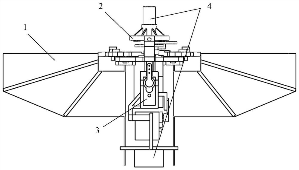
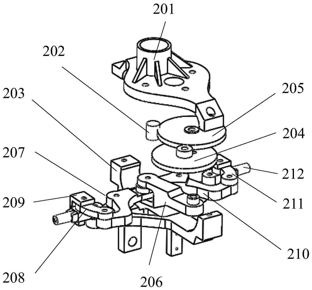
[0042] The bionic flapping-wing micro-aircraft that realizes the generation of high control moment based on the differential of the two wings and the change of the center of gravity of the steering gear includes a lift system 1 , a transmission system 2 , a control system 3 and a power system 4 .

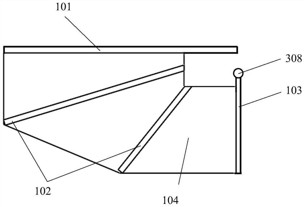
[0043] The lift system 1 is composed of two left and right flapping wings, the aerodynamic action points generated by the flapping wings do not coincide with the center of gravity, and each flapping wing is composed of a main beam 101, a flexible beam 102, a tension beam 103 and a membrane 104 . The wing membrane 104 is a flexible membrane made of polyimide material, and the front edge and the side edge of the wing membrane 104 are respectively wrapped into tubes and then fixed with an adhesive. The main beam 101 and the tension beam ...


PUM


Abstract

The invention discloses a bionic flapping-wing micro-aircraft and a control moment generation method based on the difference of two wings and the change of the center of gravity of a steering gear to realize the generation of high control moment. The aircraft includes a lift system, a transmission system, a control system and a power system. The transmission system realizes the reciprocating flapping of the wings in a small space through the combination of the distributed gear reduction gear and the crank-connecting rod. The control system respectively drives the flapping wing tension beam to move forward, backward, left, and right through two independent steering gears to effectively adjust the angle of attack of the flapping wing. The tension beam of the flapping wing of the present invention is connected with the spherical hinge device on the base, and is controlled by the roll steering gear and the pitch, which effectively increases the change range of the flapping wing's attack angle and improves the control moment generated by the flapping wing. In addition, when the bionic flapping-wing MAV performs attitude control, the rudder effect is further enhanced by controlling the deflection of the center of gravity of the steering gear, which effectively improves the control torque generated by the flapping wing.

Description

technical field [0001] The invention relates to the field of micro-aircraft, in particular to a bionic flapping-wing micro-aircraft that realizes high control torque generation based on biplane differential and center of gravity changes of steering gears. Background technique [0002] With the rapid development of MEMS processing, information remote sensing, computer science and other technologies, micro air vehicles have begun to change from concept to reality. MAVs have broad application prospects in military fields such as reconnaissance and surveillance, low-altitude patrols, and anti-terrorist blasting, as well as civilian fields such as mimic observation and fire disaster relief. At present, according to the principle of flight, MAVs can be roughly divided into three categories: fixed-wing MAVs, rotary-wing MAVs, and bionic flapping-wing MAVs. [0003] Micro air vehicles are small in size and low in flight speed, and their wings are in low Reynolds number flow during ...

Claims


Application Information

Patent Timeline
Patent Type & Authority Patents(China)
IPC IPC(8): B64C33/02B64D27/24G05D1/08
CPCB64C33/02B64D27/24G05D1/0808
Inventor 吴江浩程诚
Owner BEIHANG UNIV
Why Eureka
Try Eureka