
tilt rotor aircraft

A tilt-rotor and aircraft technology, applied in the field of tilt-rotor aircraft, can solve problems such as hidden dangers of aircraft safety, unsuitable for small tilt-rotors, hitting obstacles, etc.

Active Publication Date: 2021-08-20
HEFEI UNIV OF TECH
View PDF6 Cites 0 Cited by
  • Summary
  • Abstract
  • Description
  • Claims
  • Application Information

AI Technical Summary

Problems solved by technology

[0003] There are not many types of tilt-rotor aircraft at present, the most typical one is the V-22 "Osprey" transport aircraft, which places the engine nacelle at the end of the wing. Due to the need for vertical take-off and landing, it is generally driven by the engine The propeller can generate enough lift, and then change the attitude of the nacelle to the horizontal to realize the change of the pulling force from vertical upward to horizontal forward, but there are irregular lift changes in the transition process, which makes this type of aircraft have certain hidden dangers in safety.
[0004] In view of the above problems, the existing technical conditions are solved by a complex control system on a large tilting rotor aircraft. The cost of this solution is relatively large, and it is not suitable for small tilting rotor aircrafts. Fly to a higher altitude, and then obtain a speed that can fly horizontally in the transition section (even if it falls before falling to the ground) to solve the above problems. This method needs to fly to a higher altitude, otherwise it is easy to fall or hit the ground. to the obstacle phenomenon

Method used


Image

  • tilt rotor aircraft
  • tilt rotor aircraft
  • tilt rotor aircraft

Examples


Embodiment Construction

[0025] The present invention will be further explained below in conjunction with specific embodiments.

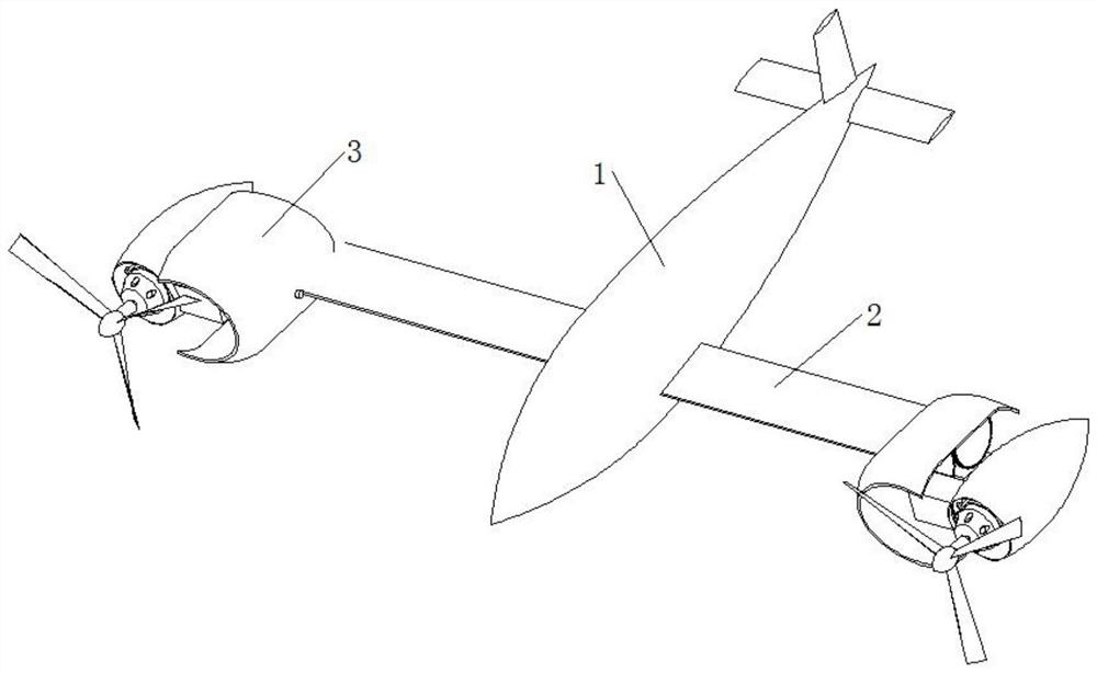
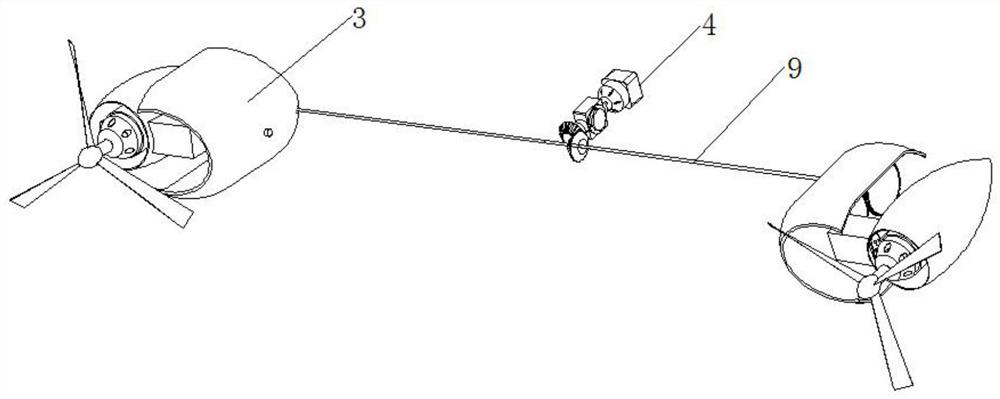
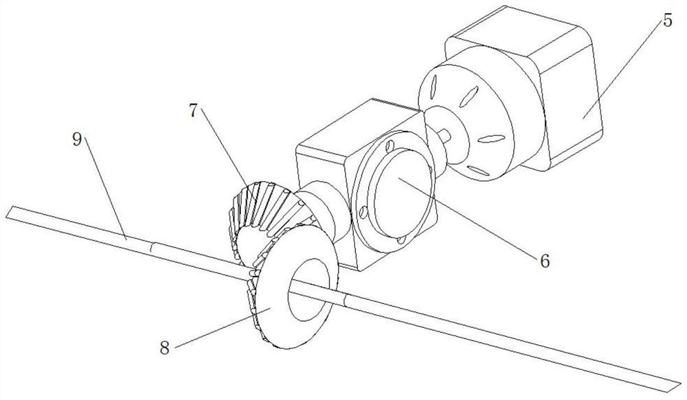
[0026] refer to Figure 1-10 , the tilt rotor aircraft proposed by the present invention comprises a fuselage 1 and wings 2 on both sides, the end of the wing 2 away from the fuselage 1 is provided with a rotating mechanism 3, and the rotating mechanism 3 includes a A propeller 14 for adjusting the pitch angle in the direction, and a rotating power mechanism 4 connected with the rotating mechanism 3 is also provided in the fuselage 1 .

[0027] Preferably, the rotating mechanism 3 includes an outer casing, the outer casing is provided with an opening on a side away from the fuselage 1, and a nacelle casing 13 is provided at the opening of the outer casing, and the nacelle casing 13 is a A rotating shaft 19 is provided on the side, and the rotating shaft 19 is rotationally connected with the nacelle housing 13, and a gear B11 is fixed on the rotating shaft 19, and the gear ...


PUM


Abstract

The invention discloses a tilting rotor aircraft, which comprises a fuselage and wings on both sides. The wings are provided with a rotating mechanism, and the rotating mechanism includes a propeller capable of adjusting the pitch angle along the flying direction of the aircraft. The aircraft The body is also equipped with a rotating power mechanism connected with the rotating mechanism. The rotating mechanism includes an outer casing. The opening of the outer casing is provided with a nacelle casing. shaft, the rotating shaft is fixed with a gear B, the nacelle housing is provided with a motor B, the output end of the motor B is provided with a propeller, the bottom of the motor B is provided with a motor base, and the motor B It is fixed on the motor base, and a motor C is provided on one side of the motor base, and a motor fixing chamber is provided on the nacelle housing, and the motor C is installed in the motor fixing chamber. The invention improves the maneuverability and operational reliability of the aircraft by changing the lift force distribution of the propeller in the flight mode.

Description

technical field [0001] The invention relates to the technical field of small aircraft, in particular to a tilt rotor aircraft. Background technique [0002] Tilting rotor aircraft can be used in the military for the transportation of personnel and materials, and it can also be used in special operations. When the airstrip is destroyed in wartime, it still does not affect its operations. In addition, it can also carry out maritime search and rescue. For civilian use, it can take advantage of its high speed and vertical take-off and landing capabilities to deliver supplies, rescue equipment and rescue personnel to the disaster area at the first time. At the same time, it can also quickly transport the injured to the nearest hospital for treatment, and its cabin space is small. Large, a temporary ambulance station can be established in the cabin, and patients can be treated to a certain extent when flying to the hospital; in addition, aerial fire fighting operations can also b...

Claims


Application Information

Patent Timeline
Patent Type & Authority Patents(China)
IPC IPC(8): B64C27/28
CPCB64C27/28
Inventor 严翔宇王红州任桐欣蔡恒欲曹睿聂良丞唐小童
Owner HEFEI UNIV OF TECH
Learn More