Horizontal-shaft wind turbine with rotating cylinder at front edge of paddle

A horizontal axis, wind turbine technology, applied in the field of wind turbines, can solve the problems of the maximum lift-to-drag ratio limitation, fixed-pitch wind turbines are prone to stall, etc., and achieve the effect of increasing the lift-to-drag ratio and improving the utilization rate of wind energy

Inactive Publication Date: 2012-07-04
SHANGHAI UNIV
View PDF0 Cites 0 Cited by
  • Summary
  • Abstract
  • Description
  • Claims
  • Application Information

AI Technical Summary

Problems solved by technology

Under the limitation of a certain speed of the wind rotor, the fixed-pitch wind turbine is more likely to stall with the increase of the incoming wind speed
After the airfoil of the wind turbine is selected, when the wind speed is constant, the maximum lift-to-drag ratio of the airfoil of the fixed-pitch wind turbine is also limited, and it cannot capture as much wind energy as possible.

Method used


Image

  • Horizontal-shaft wind turbine with rotating cylinder at front edge of paddle
  • Horizontal-shaft wind turbine with rotating cylinder at front edge of paddle
  • Horizontal-shaft wind turbine with rotating cylinder at front edge of paddle

Examples


Embodiment 1

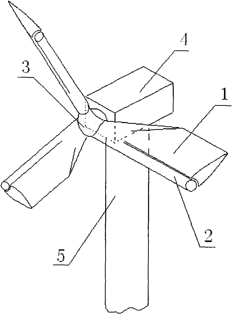
[0023] Embodiment one: see figure 1 , the horizontal axis wind turbine with a rotating cylinder at the leading edge of the blade, including a tower 5, a horizontal axis chassis 4 installed on the top of the tower 5, a hub 3 located at the front end of the chassis 4, and a blade 1 fixedly installed on the hub 3 The front edge of each blade 1 is equipped with a controllable rotating cylinder 2 that rotates forward or in a direction around its own axis, and the rotating cylinder 2 and the blade 1 rotate together with the hub 3 around the horizontal axis of the wind turbine.

Embodiment 2

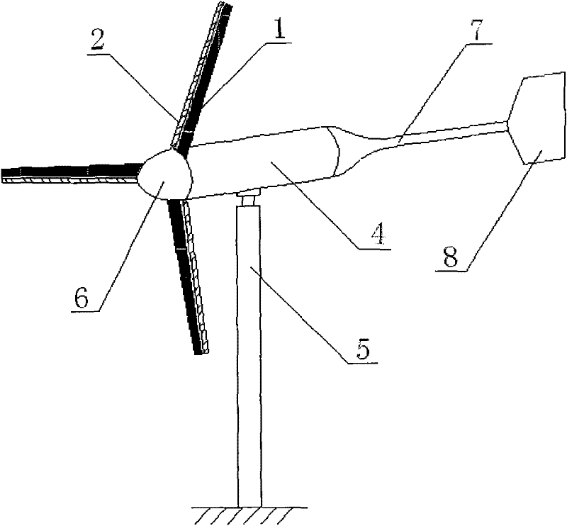
[0024] Embodiment two: see figure 2 , the horizontal axis wind turbine with a rotating cylinder at the leading edge of the blade, including a vertically installed tower 5, a horizontal axis chassis 4 installed on the top of the tower 5, a tail boom 7 and an empennage 8 at the rear of the chassis 4 1. The paddle 1 and the shroud 6 located at the front end of the chassis 4, each paddle 1 front edge is equipped with a controllable rotating cylinder 2 that rotates forward or reverse around its own axis, and the rotating cylinder 2 is connected with the paddle 1 Together with the rotor 14 in the box 4, it rotates around the horizontal axis of the wind turbine.

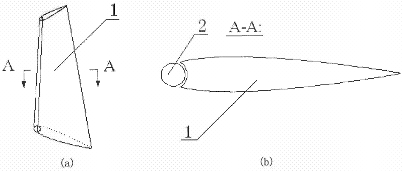
[0025] exist figure 1 , 2 , there is a certain gap δ between the blade 1 and the rotating cylinder 2 at its leading edge. δ is about 1 mm to 2 cm, depending on the size of the wind turbine, to ensure that the rotating cylinder 2 rotates independently around its own axis relative to the blade 1, such as image 3 As sho...


PUM


Abstract

The invention relates to a horizontal-shaft wind turbine with a rotating cylinder at the front edge of a paddle, which comprises a tower rack, a horizontal-shaft case, paddles and a hub or an air shield, wherein the tower rack is straightly arranged, the horizontal-shaft case is arranged at the top end of the tower rack, and the paddles and a hub or an air shield are arranged at the front end of the case. The front edge of each paddle is provided with a controllable cylinder which can forwardly or reversely rotate in the mode of winding the self axis, and the rotating cylinder and the paddle are in revolution together with a rotor in the case. The invention obtains the purpose of effectively using the wind power through regulating the rotating speed and the rotating direction of the rotating cylinder, controlling the flowing separation of air flow on the paddles and increasing the lift-drag ratio of the paddles of the wind turbine.

Description

technical field [0001] The invention relates to a wind power machine, in particular to a horizontal axis wind power machine with a rotating cylinder at the leading edge of the blade, which can improve the utilization rate of wind energy of the wind power machine. technical background [0002] At present, the airfoils of horizontal axis wind turbines are mainly selected from aviation airfoils. In order to improve the efficiency of the blades in absorbing wind energy, airfoils with a high lift-to-drag ratio are generally used, and the blades are twisted along the height. When the speed of the wind turbine is constant, as the wind speed increases, the angle of attack of the airflow on the blade also increases, until the airflow separates on the surface of the blade, the blade stalls, the wind energy absorption rate drops sharply, and the output power also rapidly reduce. Wind turbines generally have a set of control systems to adjust the output power and speed. The manufacturi...

Claims


Application Information

Patent Timeline
Patent Type & Authority Patents(China)
IPC IPC(8): F03D1/00F03D1/06
CPCY02E10/72Y02E10/721
Inventor 黄典贵罗大海陈波庄月晴蒋磊张媛媛
Owner SHANGHAI UNIV
Why Eureka
Try Eureka