An intelligent power load control system and control method

A load control and intelligent power technology, applied in the field of power system, can solve the problems of long power outage time, failure to achieve single-user optimal load management, circuit breakers and contactors unable to achieve zero-crossing switching, etc., to reduce electricity bills Effect

Active Publication Date: 2019-07-23
陆炜
View PDF10 Cites 0 Cited by
  • Summary
  • Abstract
  • Description
  • Claims
  • Application Information

AI Technical Summary

Problems solved by technology

Therefore, the prior art has the following disadvantages: only a single load is controlled, such as electric heaters, electric water heaters, electric heaters or air conditioners; It is relatively long; when circuit breakers and contactors are switched on and off, zero-cross switching cannot be realized, which has a large impact on the power grid; the existing load control is a one-way control, and the power company sends a power-off command to the load end, and two-way information exchange cannot be realized; The user optimizes load management; after the load is cut off, there is no good planning after re-commissioning, which has a large impact on the power grid; no specific positioning of the load; no temperature control for cooling and electric heating loads

Method used


Image

  • An intelligent power load control system and control method
  • An intelligent power load control system and control method
  • An intelligent power load control system and control method

Examples


Embodiment Construction

[0025] The present invention will be further described below in conjunction with the accompanying drawings and specific embodiments.

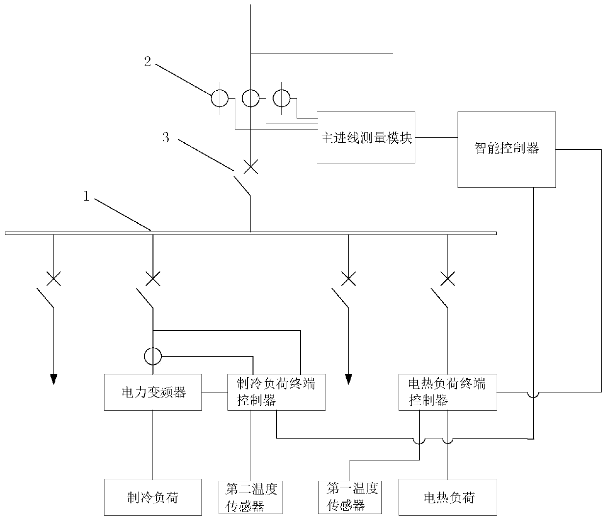
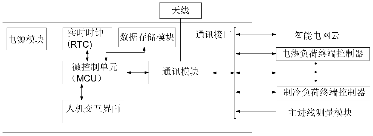
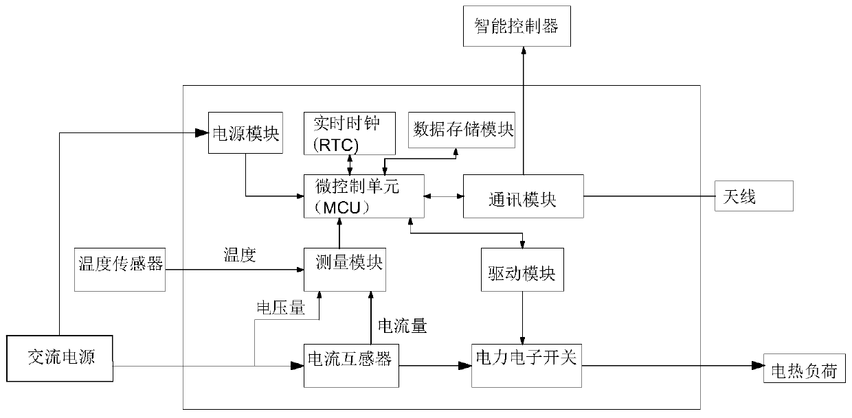
[0026] Such as figure 1 and Figure 6 As shown, 1 is a bus bar, 2 is a current transformer, and 3 is a circuit breaker. The main incoming line is divided into multiple branches, and the main incoming line and each branch are controlled by circuit breakers. The intelligent power load control system includes an intelligent controller, an electric heating load terminal controller, a cooling load terminal controller, and a main incoming line measurement module; the main incoming line measurement module is installed on the main incoming line for measuring the main incoming line Voltage and current, calculate the power value; as image 3 , the electric heating load terminal controller is installed between the electric heating load incoming switch and the electric heating load, including the built-in current transformer and power electronic switch, ...


PUM


Abstract

The invention discloses an intelligent electric power load control system and a control method. The intelligent electric power load control system comprises an intelligent controller, an electric heating load terminal controller, a refrigerating load terminal controller, and a main incoming line measurement module. The main incoming line measurement module, the electric heating load terminal controller and the refrigerating load terminal controller transmit a detected current value, a detected voltage value and a detected power value to the intelligent controller. The intelligent controller is used for calculating a power control value, and sending out control signals. The electric heating load terminal controller and the refrigerating load terminal controller are used for receiving the control signals, and then respectively controlling an electric heating load and a refrigerating load. According to the invention, a user can effectively manage the electric heating load and the refrigerating load, and the electric charge expenditure of the user in the peak period is reduced. The stability of the power grid is guaranteed. A power supply enterprise can master the load condition of the user and figure out loads for regulation and control. The accurate load prediction is carried out, and the operation cost of the enterprise is reduced.

Description

technical field [0001] The invention belongs to the field of power systems, and in particular relates to an automatic power load control device. Background technique [0002] The uncontrollable power load of power users will cause unnecessary economic losses to users and power supply companies. During the peak hours of electricity consumption, multiple devices of the user are put into use at the same time, and the overall electricity consumption is large. Due to the high electricity price during peak hours, users need to pay high electricity bills for this. On the other hand, power supply companies often need to install additional generators to meet the additional power capacity of several megawatts during peak hours. And these generators may run for hundreds of hours a year, and the rest of the time they are idle. The investment and idle time of these devices is a waste of power resources. With the development of smart grid technology, the demand side response and contro...

Claims


Application Information

Patent Timeline
Patent Type & Authority Patents(China)
IPC IPC(8): H02J3/00H02J3/14G06Q10/06G06Q50/06
CPCG06Q10/06315G06Q50/06H02J3/00H02J3/14H02J2310/14Y02B70/3225Y02P80/10Y04S10/50Y04S20/222
Inventor 陆炜
Owner 陆炜
Why Eureka
Try Eureka