Multi-section molded line cam

A multi-stage, cam technology, applied to engine components, fuel injection pumps, machines/engines, etc., can solve problems such as high fuel injection pressure and fuel injection rate, difficulty in increasing and small fuel injection volume control, and long duration

A multi-stage, cam technology, applied to engine components, fuel injection pumps, machines/engines, etc., can solve problems such as high fuel injection pressure and fuel injection rate, difficulty in increasing and small fuel injection volume control, and long duration

CN102705124AInactive Publication Date: 2012-10-03HARBIN ENG UNIV

Image

  • Multi-section molded line cam
  • Multi-section molded line cam
  • Multi-section molded line cam

Examples


Embodiment Construction

[0047] The present invention is described in more detail below in conjunction with accompanying drawing example:

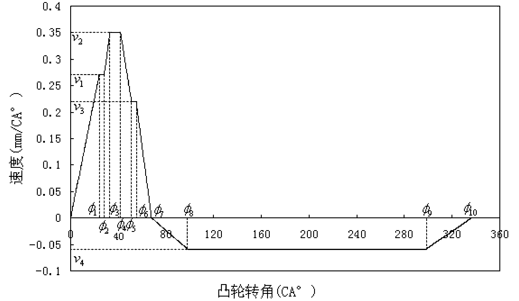
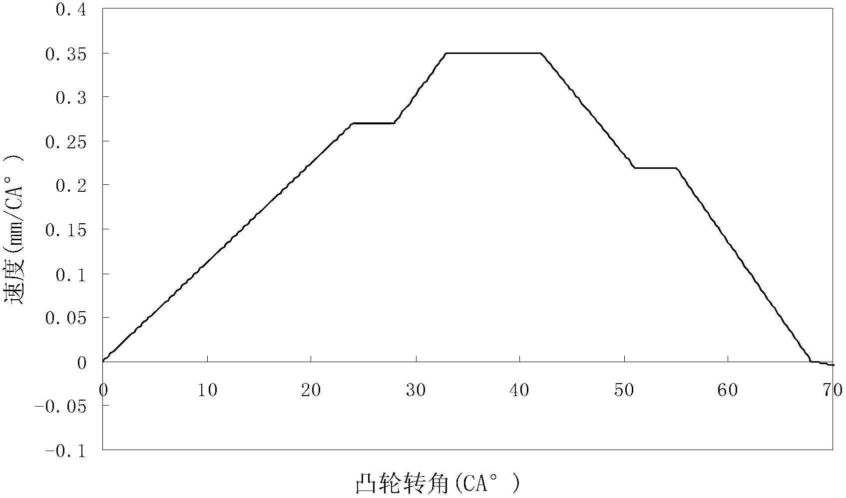
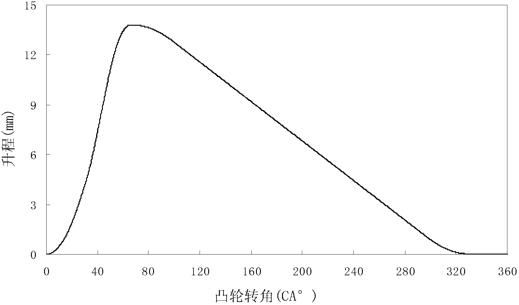
[0048] 1-3, the multi-stage cam profile of the present invention, its thrust section corresponds to two positive constant acceleration stages, three positive constant velocity stages and two forward constant deceleration stages of the movement law of the plunger follower stage, in which the second constant velocity stage has a higher speed and a longer duration than the other two constant velocity stages; the return section of the cam corresponds to the reverse constant acceleration stage and reverse constant velocity deceleration phases such as phase and reverse. Its working section is the three constant speed stages of the thrust section, the second constant acceleration stage and the first constant deceleration stage. The speed curve and lift curve are shown in Figure 1 and Figure 2 respectively. The equations of motion for each segment of the plunger follower...


PUM


Abstract

The invention aims to provide a multi-section molded line cam, which comprises an actuating travel section and a return travel section. The actuating travel section corresponds to two forward uniform acceleration stages, three forward constant speed stages and two forward uniform deceleration stages of movement rules of a plunger driven part, and the return travel section corresponds to a backward uniform acceleration stage, a backward constant speed stage and a backward deceleration stage of the movement rules of the plunger driven part. A working section comprises the three constant speed stages, the second uniform acceleration stage and the first uniform deceleration stage of the actuating travel section. The speed of the first constant speed stage of the working section is v1, the speed of the second constant speed stage of the working section is v2, the speed of the third constant speed stage of the working section is v3, and the speed of the backward constant speed stage is v4. The oil injection pressure and oil injection speed of main injection are increased, different requirements of oil injection of each stage for the oil injection pressure and the oil injection speed during multiple injection are combined, and the aims of lowering the working noise of an engine, reducing the emissions of pollutants and improving an oil injection atomization effect are fulfilled.

Description

technical field [0001] The present invention relates to a cam, in particular to a cam of an engine. Background technique [0002] In the traditional technology, the fuel supply pump cam used in the electronic control fuel injection system of diesel engine is a constant velocity cam, and its thrust section corresponds to the positive constant acceleration, forward constant velocity and forward constant deceleration stages of the plunger follower movement law, and the return stroke The segment corresponds to the reverse constant acceleration, reverse constant velocity and reverse deceleration stages of the motion law of the cam plunger follower. Its working section is the positive constant velocity stage. The constant velocity cam has been widely used in the actual fuel injection system, and it has the advantage of being easy to control the injection law, but there are also disadvantages: with the increasingly stringent emission regulations and the increasing requirements for...

Claims


Application Information

Patent Timeline
03 Oct 2012
Publication
CN102705124A
IPC
F02M59/10; F02M59/28
Inventors
范立云; 王昊