Heat exchanger and flat heat-exchanging tube

A technology of heat exchange tubes and heat exchangers, which is applied in the direction of tubular elements, heat exchange equipment, evaporators/condensers, etc., can solve the problems of insufficient channel arrangement, few channels, and unfavorable heat exchange, so as to improve rationality, The effect of avoiding freezing and smooth drainage

Active Publication Date: 2012-10-24
TIANJIN SANDEN AUTO AIR CONDITIONING
View PDF3 Cites 5 Cited by
  • Summary
  • Abstract
  • Description
  • Claims
  • Application Information

AI Technical Summary

Problems solved by technology

[0006] In the flat tube structure of the prior art, the flat tubes all have passages for dispersing and flowing the refrigerant, and the cross-sections of the passages are rectangular, so eddy currents are easily generated at four right angles (especially when used as an evaporator). ), so it is unfavorable to heat exchange; some channels have a circular or elliptical cross-section. The problem is that such channels cannot be arranged in many flat tubes, and there are few channels, which restricts the further improvement of the heat exchange capacity of the heat exchanger.

Method used


Image

  • Heat exchanger and flat heat-exchanging tube
  • Heat exchanger and flat heat-exchanging tube
  • Heat exchanger and flat heat-exchanging tube

Examples


Embodiment Construction

[0061] Below in conjunction with preferred embodiments, the specific implementation, features and effects provided by the present invention are described in detail as follows; for the purpose of simplicity and clarity, the description of known technologies is appropriately omitted below to avoid unnecessary details Affect the description of this technical solution.

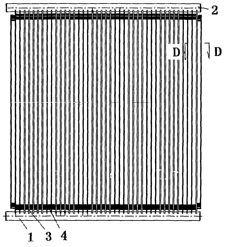
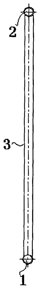
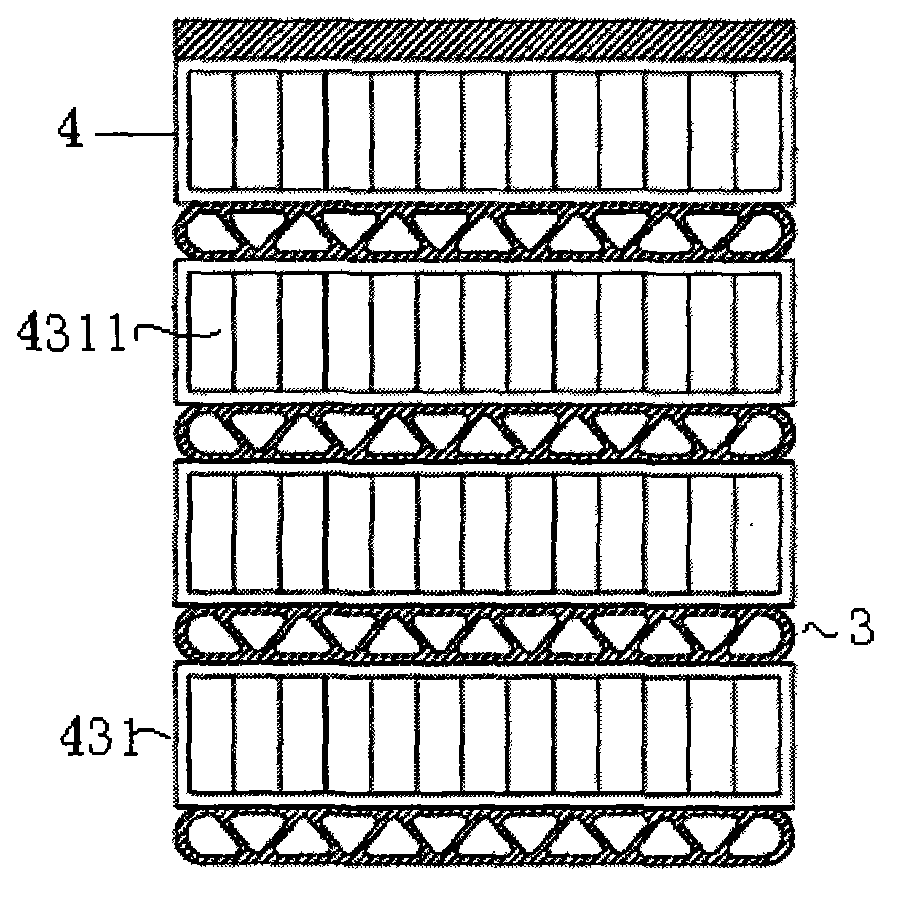
[0062] see Figure 1-8 As shown, a flat tube structure of a heat exchanger and its heat exchanger include a first liquid collection pipe 1, a second liquid collection pipe 2, and a plurality of devices installed between the two liquid collection pipes to accommodate refrigerant passage. a flat heat exchange tube 3, and a fin strip 4 installed between the flat heat exchange tubes for heat dissipation;

[0063] The flat heat exchange tubes 3 are parallel to each other and are separated from each other by the same predetermined distance. The two ends of the flat heat exchange tubes are provided with tooling shrinkag...


PUM


Abstract

The invention provides a heat exchanger and a flat heat-exchanging tube and relates to a structure of the flat tube of a fine channel heat exchanger. The application of the structure of the flat tube of the fine channel heat exchange is the divisional application of the heat exchanger and the structure of the flat tube of the heat exchanger, wherein the number of the divisional application is 200910070901.7. One separation plate is arranged between two adjacent channels; every two adjacent separation plates form a triangular area of a triangular channel, and the two adjacent separation plates form the triangular channel together with the first side wall or second side wall of the heat-exchanging tube; two adjacent triangular channels are configured symmetrically to form a parallelogram; and the shutter area of the heat exchanger with the flat tube is formed by a predetermined number of windows which are configured on a straight area, wherein the windows have the same structure and are opened towards air flow direction so that the air can flow downwards obliquely along the air flow direction. Due to the improvement on the channels of the flat tube, the heat transfer efficiency of the heat exchanger is improved effectively, and due to the improvement on the fin strip structure, the condensed water can be discharged smoothly without being iced, and the heat exchanging efficiency can be improved more effectively.

Description

technical field [0001] The invention belongs to the field of air conditioning, relates to a flat tube structure of a fine channel heat exchanger, and is suitable for evaporators of household air conditioners, commercial air conditioners and central air conditioners. This case is a divisional application of "200910070901.7 Flat tube structure of heat exchanger and its heat exchanger". Background technique [0002] The engineering background of microscale heat transfer problems comes from the cooling of high-density electronic devices in the 1980s and the flow and heat transfer problems in microelectromechanical systems that emerged in the 1990s. Its characteristic is that when the scales of space and time are miniaturized, many physical phenomena appear that are different from conventional scales. Micro-channel radiator is a technology that the industry has been researching and using. It is reported that as early as the 1980s, scientists proposed the concept of "micro-channe...

Claims


Application Information

Patent Timeline
Patent Type & Authority Applications(China)
IPC IPC(8): F25B39/02F28F1/02
Inventor 魏庆奇陈启
Owner TIANJIN SANDEN AUTO AIR CONDITIONING
Why Eureka
Try Eureka