
parabolic gauge

A parabolic, vertical line technique

Active Publication Date: 2015-10-21
TANGSHAN ZHENGFENG IRON & STEEL CO LTD
View PDF9 Cites 0 Cited by
  • Summary
  • Abstract
  • Description
  • Claims
  • Application Information

AI Technical Summary

Problems solved by technology

[0002] There is no such simple and convenient parabolic gauge at present.

Method used


Image

  • parabolic gauge
  • parabolic gauge
  • parabolic gauge

Examples


Embodiment Construction

[0021] Below in conjunction with accompanying drawing and embodiment the present invention will be further described:

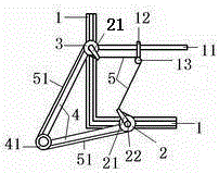
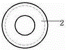
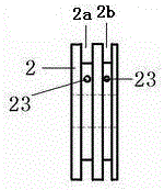
[0022] Such as figure 1 and Figure 4 As shown, the present invention mainly consists of coordinate frame 1, horizontal line wheel 2, vertical line wheel 3, V-shaped frame 4, telescoping line 5, coil spring 6, sliding bar 11, slider 12, pen cap 13, thread nozzle 21, horizontal liner Wire wheel fixing button 22, rotating wheel 41 and connecting wire 51 form. The coordinate frame 1 is L-shaped, and a chute is arranged on the coordinate frame 1 . The V-shaped frame 4 is formed by combining two straight strip-shaped objects through the rotating wheel 41, and the two straight-strip-shaped objects of the V-shaped frame 4 can rotate around the rotating wheel 41; One end of frame 4, longitudinal wire wheel 3 is located at the other end of V-shaped frame 4;

[0023] Such as image 3 As shown, the outer circumference of the horizontal line wheel 2 is provided with...


PUM


Abstract

The invention discloses a parabola gauge. The parabola gauge mainly consists of a coordinate frame 1, an abscissa wheel 2, an ordinate wheel 3, a V-shaped frame 4, a telescopic line 5, a coil spring 6, a sliding rod 11, a sliding block 12, a pen cap 13, line nozzles 21, an abscissa wheel fixing knob 22, a rotating wheel 41 and a connecting line 51. Due to the resetting tension of the coil spring, both the telescopic line and the connecting line are in a tensioned state. Firstly a midpoint of the telescopic line between the two line nozzles is fixed on the pen cap, then the abscissa wheel is fixed at a corresponding position on the coordinate frame by using the abscissa wheel fixing knob according to parameters of a parabola and a drawing pen is inserted into the pen cap, the sliding rod is moved upwards, the whole telescopic line is always maintained to be in the tensioned state in the moving process, and then a track of the drawing pen is the parabolic trajectory.

Description

technical field [0001] The invention relates to an instrument, in particular to a parabola gauge for drawing a parabola curve. Background technique [0002] There is no such simple and convenient parabolic gauge at present. Contents of the invention [0003] The problem to be solved by the present invention is to provide a parabolic gauge with simple structure, convenient operation and accurate line drawing. [0004] In order to solve the above technical problems, the technical solution of the present invention is as follows: [0005] A parabolic gauge, the structure of which includes a coordinate frame, a horizontal line wheel, a vertical line wheel, a V-shaped frame, a telescopic line, a coil spring, a sliding rod, a slider, a pen cover, a thread mouth, a horizontal line wheel fixing button, a rotating wheel and a connecting Wire. [0006] The coordinate frame is L-shaped, and a chute is arranged on the coordinate frame. The V-shaped frame is formed by combin...

Claims


Application Information

Patent Timeline
Patent Type & Authority Patents(China)
IPC IPC(8): B43L11/00
Inventor 郑福建
Owner TANGSHAN ZHENGFENG IRON & STEEL CO LTD
Learn More