
Portable clothes drying device
A clothes dryer and portable technology, which is applied in the direction of household clothes dryers, other drying devices, washing devices, etc., can solve the problems of clean clothes that are easy to emit peculiar smell, and the drying equipment is bulky and difficult to carry around, so as to achieve convenience Fast drying, small space, guaranteed drying effect
- Summary
- Abstract
- Description
- Claims
- Application Information
AI Technical Summary
Problems solved by technology
Method used
Image

Examples
Embodiment 1
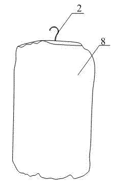
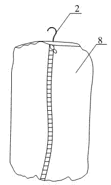
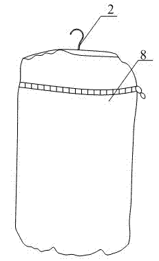
[0045] The working principle of the clothes dryer is to dry the washed and dehydrated clothes through a heating device in a relatively closed space. In the prior art, the structure of the clothes dryer is similar to that of a clothes hanger, which takes up a lot of space, cannot be folded, and is inconvenient to carry on business trips and travels. In view of the above defects, this embodiment provides a portable clothes dryer. On the basis of the working principle of the existing clothes dryer, the structure of the existing clothes dryer in contact with the ground for support is improved to use a hook Suspended structure, then the clothes hanger is designed as an umbrella shape, and is movably connected with the support mechanism, which mainly consists of two parts: the clothes dryer skeleton and the clothes drying cover 8 covered outside it. The external structure of the present invention's use state is as figure 1 As shown, its top view is as Figure 8 shown; and the dryi...
Embodiment 2
[0054] There are many ways to support the structure of the portable clothes dryer, such as Figure 10 As shown, the difference between this embodiment and Embodiment 1 is that the support mechanism includes a hollow support rod 6, and a tape reel 7 that is arranged on the top of the support rod 6 and has a tape measure line inside. The clothes hanger 1 is located on the tape reel 7. Around; Wherein, the structure of tape measure reel 7 is as Figure 11 As shown, its structure is similar to common tape measures on the market. A through hole is provided on the outer wall of the tape measure reel 7 , and the end of the tape measure line passes through the through hole, and then passes through the support rod 6 and is connected with the heating device 3 . By adjusting the tape reel 7, and then adjusting the telescopic length of the tape line, the heating device can move up and down in the vertical direction, so as to adjust the distance between the heating device and the clothes t...
Embodiment 3
[0057] Such as Figure 13 As shown, the difference between this embodiment and the above-mentioned embodiments is that the supporting mechanism is composed of a hollow connecting rod 11 and a telescopic connecting rod 9 arranged in the connecting rod 11 and whose upper end is on the same plane as the connecting rod 11; wherein, The connecting rod 11 has the same structure as the support rod 6 in Embodiment 2. On the basis of the above structure, this embodiment also has a stepped hole in the middle of the heating device 3, such as Figure 15 As shown, the bottom end of the telescopic connecting rod 9 passes through the step hole, and the bottom end of the telescopic connecting rod 9 is also provided with a baffle plate 10; the baffle plate 10 can perform piston movement in the step hole together with the connecting rod 11; In the state of use, the baffle plate 10 is against the upper end of the through hole with a larger diameter in the stepped hole, so that the heating device...
PUM
 Abstract
Description
Claims
Application Information