Check patentability & draft patents in minutes with Patsnap Eureka AI!

Projector

A technology of projection device and projection surface, applied in projection devices, optics, instruments, etc., can solve problems such as easy obstruction of wires

Active Publication Date: 2015-04-22
RICOH KK
View PDF2 Cites 0 Cited by
  • Summary
  • Abstract
  • Description
  • Claims
  • Application Information

AI Technical Summary

Problems solved by technology

[0006] However, as described in Patent Document 2, a short-distance projection type projection device is provided with a plurality of connectors on the side wall of the frame on the opposite side of the projected surface, and the wires connected to the plurality of connectors will hang down from the side wall. To the side of the above-mentioned space, and if someone enters the space, the wire will easily hinder the person, such as being caught by the wire

Method used


Image

  • Projector
  • Projector
  • Projector

Examples


Embodiment Construction

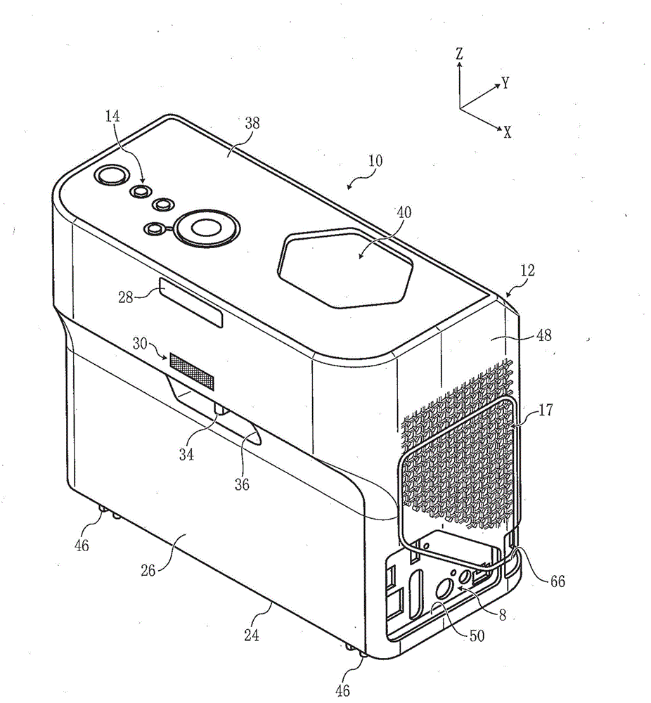
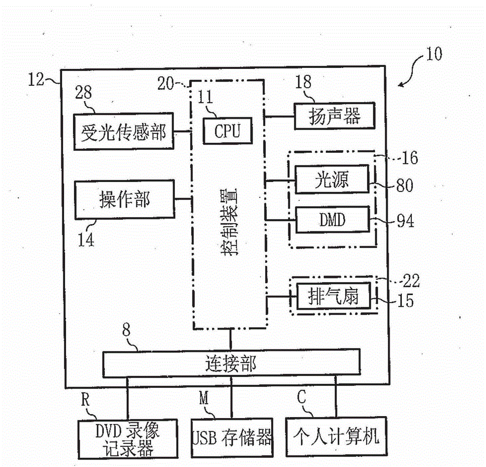
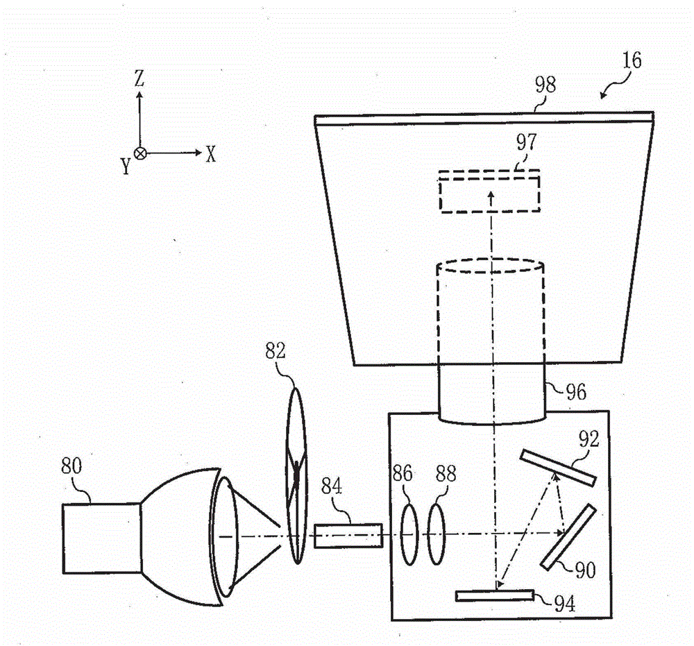
[0032] The following is based on Figure 1 to Figure 14 An example of an embodiment of the present invention will be described. figure 1 It is a perspective view of a projection device 10 as an electronic device according to an embodiment. figure 2 is a structural block diagram of the projection device 10 .

[0033] When the projection device 10 is used, for example, it is placed on the upper surface of the installation table P provided on the plane F parallel to the horizontal plane.

[0034] As an example, the projection device 10 includes a frame body 12, a projection optical system 16 housed in the frame body 12, a light receiving sensor portion 28, an operation portion 14, a cooling unit 22, a speaker 18, a connection portion 8 for connecting external devices, and the above-mentioned The control device 20 etc. that each part is connected. The projection optical system projects a beam of light onto a screen S based on input information from peripherals such as a DVD re...


PUM


Abstract

A projector (10) including a housing (12), an image projection unit (16), and a plurality of connection ports including a power connection port (64). The housing (12) has a top face (38), and a first face and a second face adjacent to each other, and a light projection port (40) on the top face (38). The image projection unit (16) includes an optical system to project light corresponding to image data, via the light projection port (40) disposed on the top face (38), in an upward oblique direction with respect to the first face. The plurality of connection ports is disposed on the second face. The power connection port (64) is disposed at a position in the second face closest to the first face side.

Description

technical field [0001] The present invention relates to a projection device, and more particularly to a projection device that projects a light beam based on image information through a light projection port on an upper wall of a housing. Background technique [0002] The projection device in the prior art usually refers to the so-called short-distance projection type projection device, that is, as disclosed in Patent Document 1 (JP Unexamined Patent Publication No. 2008-158495), it is placed through the light projection port on the upper wall of the frame. A light beam projection device based on image information is projected obliquely above the frame on a projection surface such as a screen. [0003] The projection device is installed close to the projected surface, and the space on the opposite side of the projection device from the projected surface is usually used as a passage or the like. [0004] In addition, in the projection device disclosed in Patent Document 2 (J...

Claims


Application Information

Patent Timeline
Patent Type & Authority Patents(China)
IPC IPC(8): G03B21/00G03B21/14G03B21/28
CPCG03B21/145G03B21/16
Inventor 诸星博
Owner RICOH KK
Features
  • R&D
  • Intellectual Property
  • Life Sciences
  • Materials
  • Tech Scout
  • Unparalleled Data Quality
  • Higher Quality Content
  • 60% Fewer Hallucinations
Learn More