Return control system

A recovery control and urea water technology, which is applied in exhaust gas treatment, mechanical equipment, engine components, etc., can solve the problems of poor movement of the quantitative valve 104, unstable pressure, and lack of recovery control, etc., to achieve the effect of eliminating poor movement

Active Publication Date: 2015-03-25
ISUZU MOTORS LTD
View PDF6 Cites 0 Cited by
  • Summary
  • Abstract
  • Description
  • Claims
  • Application Information

AI Technical Summary

Problems solved by technology

[0013] Since the quantitative valve 104 is arranged in the engine exhaust pipe where the high-temperature exhaust gas flows, if the quantitative valve 104 becomes high temperature, the urea water in the quantitative valve 104 also becomes high temperature, as Figure 8 As shown in (a), the urea water in the quantitative valve 104 is crystallized, and the valve body 129 is stuck, or like Figure 8 As shown in (b), the crystallized solid 134 of the urea water is sandwiched between the valve body 129 and the valve seat of the hydraulic cylinder 127, and the injection of the urea water cannot be stopped, resulting in malfunction of the metering valve 104, and proper injection cannot be performed. Problems such as urea water injection control
[0014] Moreover, when the liquid delivery pipeline connecting the urea tank and the supply assembly is blocked by some foreign matter, etc., there is a problem that the pressure of the urea water in the quantitative valve 104 is not constant—that is, the pressure does not rise, and the urea water does not start to be sprayed.
[0015] However, recovery control from such problems to a normal state has so far not

Method used


Image

  • Return control system
  • Return control system
  • Return control system

Examples


Embodiment Construction

[0030] Preferred embodiments of the present invention will be described below with reference to the drawings.

[0031] First, an SCR system mounted on a vehicle will be described.

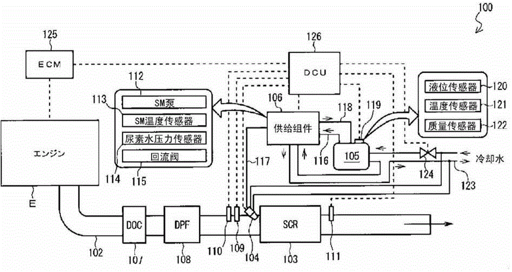
[0032] Such as figure 1 As shown, the SCR system 100 mainly includes: an SCR device 103 arranged in the exhaust pipe 102 of the engine E, a metering valve (urea injection device, metering assembly) for injecting urea water on the upstream side of the SCR device 103 (the upstream side of the exhaust gas) ) 104, a urea tank 105 for storing urea water, a supply assembly 106 for supplying the urea water stored in the urea tank 105 to the dosing valve 104, a DCU (Dosing Control Unit) 126 for controlling the dosing valve 104 or the supply assembly 106, etc.

[0033] In the exhaust pipe 102 of the engine E, a DOC (Diesel Oxidation Catalyst) 107 , a DPF (Diesel Particulate Filter) 108 , and an SCR device 103 are arranged sequentially from the upstream side of the exhaust gas to the downstream side. DOC1...


PUM


Abstract

The present invention provides a recovery control system that allows a dosing valve to recover from a malfunction to a normal state or a liquid feed line through which urea solution is fed to recover from clogging to a normal state. A recovery control system for allowing a dosing valve 104 to recover from a malfunction to a normal state has abnormality detection means of detecting an abnormality of the dosing valve 104 and recovery control means of controlling a supply module 106 to feed urea solution in the dosing valve 104 back to a urea tank 105 when the abnormality detection means detects an abnormality of the dosing valve 104.

Description

technical field [0001] The present invention relates to a recovery control system for eliminating malfunction of a metering valve or blockage of a liquid delivery pipeline for delivering urea water and returning to a normal state. Background technique [0002] Used to purify NO in the exhaust gas of diesel engines X developed an SCR system using an SCR (Selective Catalytic Reduction, Selective Catalytic Reduction) device. [0003] The SCR system provides the urea water stored in the urea tank to the exhaust gas upstream of the SCR, uses the heat of the exhaust gas to generate ammonia, and uses the ammonia to reduce NO on the SCR catalyst X A system that performs purification (see, for example, Patent Document 1). [0004] use here Figure 6 Describe the process of producing ammonia from urea water. [0005] Such as Figure 6 As shown, if the temperature of urea water becomes higher than the boiling point, its moisture will start to evaporate, and gas will be generated thr...

Claims


Application Information

Patent Timeline
Patent Type & Authority Patents(China)
IPC IPC(8): F01N3/18B01D53/94F01N3/08
CPCF01N2610/1453Y02T10/24F01N3/208F01N11/00B01D2251/2067F01N2610/02F01N2550/05F01N2610/1493Y02A50/20Y02T10/12
Inventor 小野寺贵夫岩下拓朗岭泽正信
Owner ISUZU MOTORS LTD
Why Eureka
Try Eureka