horn antenna

A horn antenna and horn technology, applied in the directions of antennas, waveguide horns, electrical components, etc., can solve the problem that the phase inconsistency cannot be fundamentally eliminated, and achieve the effect of light weight, simple structure and small structure

Active Publication Date: 2016-01-13
KUANG CHI INST OF ADVANCED TECH +1
View PDF2 Cites 0 Cited by
  • Summary
  • Abstract
  • Description
  • Claims
  • Application Information

AI Technical Summary

Problems solved by technology

In order to reduce the phase inconsistency on the mouth surface, the method often used is to change the head of the horn or the length of the horn, but the above methods can only reduce the phase difference, and cannot fundamentally eliminate the adverse effects of phase inconsistency

Method used


Image

  • horn antenna
  • horn antenna
  • horn antenna

Examples


Embodiment Construction

[0029] The present invention will be described in further detail below in conjunction with the embodiments and the accompanying drawings, but the embodiments of the present invention are not limited thereto.

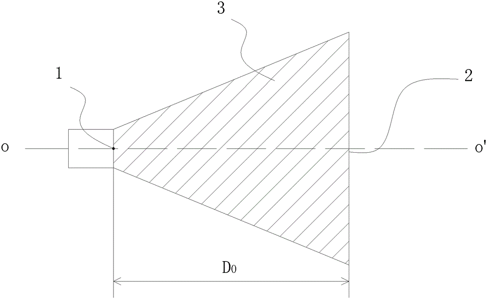
[0030] Such as figure 1 Shown is a horn antenna, which includes: a feed 1 and a horn 2, and the horn is filled with a metamaterial medium 3 having a refractive index distribution.

[0031] The horn antenna emits electromagnetic wave signals from the feed source 1, and enters the metamaterial medium 3 through the horn 2 for electromagnetic wave convergence, and through the refractive index distribution inside the metamaterial medium 3, the horn antenna has the characteristics of high gain and good directivity .

[0032] In order to make the horn antenna have the above-mentioned characteristics, that is to say, to ensure that the electromagnetic waves have the same phase when the electromagnetic waves are emitted from the horn mouth surface, that is, equal phase transmiss...


PUM


Abstract

The invention relates to a horn antenna which comprises a feed source and a horn, wherein metamaterial media with refractive index distribution are filled in the horn, each point in the metamaterial media is provided with a metamaterial unit, and each metamaterial unit comprises an artificial microstructure and a unit base material for the artificial microstructure to be attached to. The horn antenna is simple in structure, low in manufacture price, high in gains, good in directionality, strong in pressure resistance, free of electric breakdown, small in structure, light in weight and flexible.

Description

technical field [0001] The present invention relates to the field of wireless communication, and more specifically, relates to a horn antenna. Background technique [0002] The horn antenna is a microwave antenna with a circular or rectangular cross-section that is gradually opened at the end of the waveguide. It is also a planar antenna. The function of the horn is to generate a uniform phase wavefront on a larger diameter than the waveguide, so as to obtain higher directivity. Because of its easy design, manufacture and relatively low cost, the horn antenna has a wide range of applications in real life. [0003] The main thing that limits the directivity of the horn antenna is the phase inconsistency on the face of the horn mouth. When the electromagnetic wave enters the horn throat from the waveguide to the bell mouth surface, the wave surface of the electromagnetic wave changes from a plane to a spherical surface, and the phases of the electromagnetic waves on the bell...

Claims


Application Information

Patent Timeline
Patent Type & Authority Patents(China)
IPC IPC(8): H01Q13/02H01Q15/00H01Q15/02H01Q19/08
Inventor 刘若鹏季春霖岳玉涛杨树坤
Owner KUANG CHI INST OF ADVANCED TECH
Why Eureka
Try Eureka