A shell and tube heat exchanger

A shell-and-tube heat exchanger, heat exchanger technology, applied in the direction of heat exchanger types, indirect heat exchangers, tubular elements, etc., can solve the problems of reducing heat exchange efficiency, increasing flow resistance, and large flow resistance in tubes, etc. Achieve the effect of increasing the utilization rate of the heat exchange area, reducing the power and head, and improving the heat exchange efficiency

Active Publication Date: 2015-09-09
佛山市步鹿节能科技有限公司
View PDF7 Cites 0 Cited by
  • Summary
  • Abstract
  • Description
  • Claims
  • Application Information

AI Technical Summary

Problems solved by technology

However, this shell-and-tube heat exchanger also has some shortcomings, mainly: first, the heat exchange tube adopts a round tube, and under the condition of low flow rate in the tube, the thermal resistance of the boundary layer is large and the heat transfer coefficient is low; However, under the condition of high flow rate, the flow resistance in the pipe is relatively large.
Second, the traditional single-bow baffle heat exchanger has a flow dead zone at the junction of the baffle and the shell, which easily causes the fluid to swirl, increases the flow resistance, and easily causes fouling, reducing the heat exchange efficiency
Third, the traditional single-bow baffle is difficult to cooperate with non-circular enhanced heat transfer tubes, which greatly limits the application of enhanced heat transfer technology
These problems have seriously affected the heat transfer efficiency of traditional heat exchangers. In order to improve their efficiency, people have continuously improved their structures, but the results are not ideal.

Method used


Image

  • A shell and tube heat exchanger
  • A shell and tube heat exchanger
  • A shell and tube heat exchanger

Examples


no. 1 example

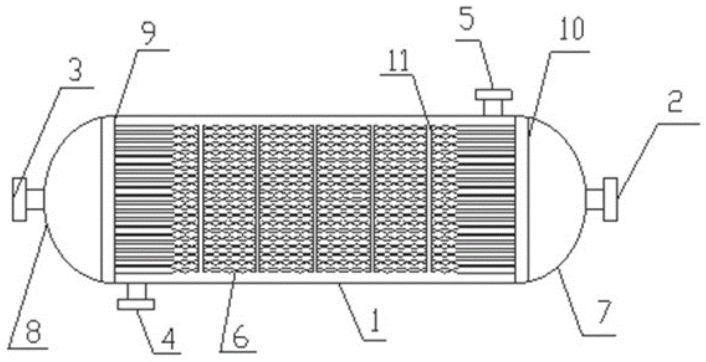
[0028] see figure 1 , the present invention provides a first embodiment of a shell-and-tube heat exchanger, including a shell 1, a fluid inlet 2 in the tube, a fluid outlet 3 in the tube, a fluid inlet 4 outside the tube, a fluid outlet 5 outside the tube, and a heat exchange tube 6 , head 7,8, tube sheet 9,10 and strapping 11. The seal heads 7 and 8 are arranged at both ends of the heat exchanger, and have an inlet 2 and an outlet 3 for the fluid in the pipe, and an inlet 4 and an outlet 5 for the fluid outside the pipe are arranged on the outer wall of the shell. The heat exchange tubes 6 are arranged in the shell 1, and both ends are connected with the tube sheets 9, 10, and the shell 1 does not have a baffle. The heat exchange tube 6 is a straight tube.

[0029] Preferably, both ends of the heat exchange tube 6 are sealed and connected to the tube sheets 9 and 10; the binding strap 11 is a steel strap.

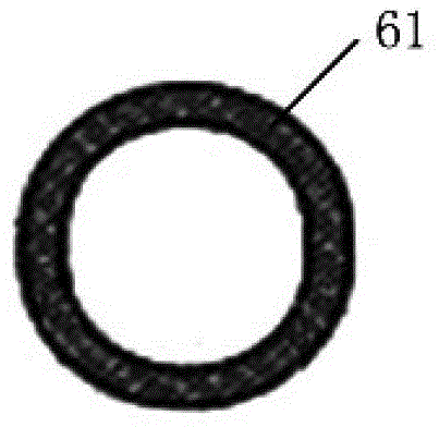
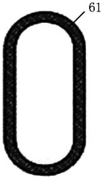
[0030] combine Figure 2 to Figure 7 , the heat exchange tubes 6 ...


PUM


Abstract

The invention discloses a pipe casing type heat exchanger which comprises a casing, a heat exchange pipe arranged in the casing and sealing heads arranged at two ends of the heat exchanger. An inside-pipe fluid inlet and an inside-pipe fluid outlet are arranged on the sealing heads, and an outside-pipe fluid inlet and an outside-pipe fluid outlet are arranged on the casing. Two ends of the heat exchange pipe are connected with a pipe plate, the heat exchange pipe is a pipe bundle composed of at least one transformation pipe, and the transformation pipes are mutually contacted in a certain distance to form a self-support structure. The pipe casing type heat exchanger is capable of achieving the effect that fluid inside and outside the pipes flows in parallel. The heat exchanger has the advantages of being high in heat exchange efficiency, small in resistance, not apt to scaling, small in vibration and the like.

Description

technical field [0001] The invention relates to the technical field of heat exchangers, in particular to a shell-and-tube heat exchanger. Background technique [0002] In the existing ordinary shell-and-tube heat exchangers, the traditional heat exchangers generally use circular heat exchange tubes with equal diameters, and arcuate baffles are added on the shell side to support the tube bundle and enhance the fluid disturbance in the shell side. There are two major defects in this type of heat exchanger. The first is that the fluid performs a "Z" baffle movement on the shell side, and the flow resistance is large, and the rear of the baffle is easy to form a backflow dead zone, resulting in insufficient heat transfer area. use. The shell-side fluid flows in the shell outside the heat exchange tube to realize the heat exchange between the cooling medium and the cooled medium. The shell side is equipped with baffles to support the heat exchange tubes and strengthen the fluid...

Claims


Application Information

Patent Timeline
Patent Type & Authority Patents(China)
IPC IPC(8): F28D7/00F28F1/00
Inventor 朱冬生
Owner 佛山市步鹿节能科技有限公司
Why Eureka
Try Eureka