Method for controlling switch

A technology for controlling switches and switches, applied in electronic switches, electrical components, pulse technology, etc., can solve problems such as sensing malfunction, easy environmental interference, and different reflectivity.

Inactive Publication Date: 2013-05-01
CORETRONIC
View PDF9 Cites 1 Cited by
  • Summary
  • Abstract
  • Description
  • Claims
  • Application Information

AI Technical Summary

Problems solved by technology

[0007] 1. The directivity is too high: the directivity of the infrared light source is too high, and it can only detect objects directly in front, so when the target is not directly in front, it cannot be detected
[0008] 2. The environment is easy to interfere: because the principle of the blocking infrared sensing device is that the object reflects the infrared light source
If in the erection environment, there happens to be objects in front that reflect the infrared light source, it will cause sensing malfunction
[0009] 3. Substances have different reflectivity: Since the blocking infrared sensing device emits infrared light sources and detects through object reflection, but the reflection characteristics of the object surface are different (such as different clothing materials and colors), resulting in inconsistent sensitivity. Objects with different surface reflective properties may be touched correctly at different distances
[0010] Due to the above problems, blocking infrared sensing products can only be installed in places with simple environments and simple usage methods, such as urinals or sinks in the bathroom.

Method used


Image

  • Method for controlling switch
  • Method for controlling switch
  • Method for controlling switch

Examples


Embodiment Construction

[0050]The aforementioned and other technical content, features and effects of the present invention will be clearly presented in the following detailed description of preferred embodiments with accompanying drawings. The directional terms mentioned in the following embodiments, such as: up, down, left, right, front or back, etc., are only referring to the directions of the drawings. Accordingly, the directional terms are used to illustrate and not to limit the invention.

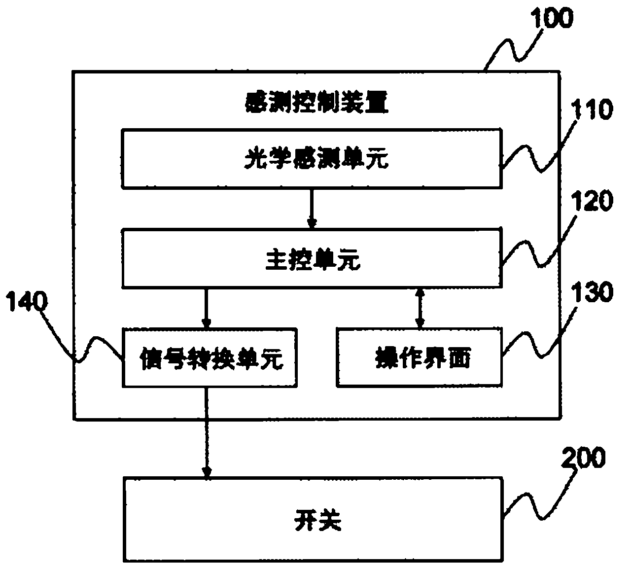
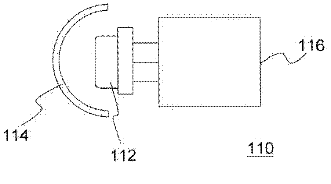
[0051] Please refer to figure 1 and figure 2 . figure 1 is a functional block diagram of the sensing control device 100 according to the embodiment of the present invention, figure 2 for figure 1 A schematic diagram of the optical sensing unit 110. The sensing control device 100 includes an optical sensing unit 110 and a main control unit 120 . The optical sensing unit 110 is used to detect environmental variables, and the main control unit 120 is used to control the operation of the switch 200 accor...


PUM


Abstract

The invention discloses a method for controlling a switch. The method comprises the steps of providing an optical sensing unit to detect an environment variable, and switching on the switch when the environment variable is not less than a first threshold; switching off the switch when the environment variable is still less than the first threshold in a first unit time after the switch is switched on; and switching off the switch when the environment variable is still less than a second threshold in a second unit time after the switch is switched on. The first threshold is more than the second threshold, but the first unit time is more than the second unit time.

Description

technical field [0001] The present invention relates to a method of controlling a switch, and in particular to a method of controlling a switch based on environmental changes. Background technique [0002] The control system of electrical equipment can be divided into traditional manual control system and modern automatic control system according to the control mode. For traditional manual control switches, users have to manually turn on, turn off or adjust the state of electrical appliances according to their current needs. As for automated electrical devices, such as automatic lighting fixtures, they can be automatically adjusted according to user needs (for example, ambient light brightness or whether the human body is within the use range), and manual methods are omitted. In addition, the automatic control system can also prevent the user from forgetting to turn off the switch, resulting in unnecessary power consumption. [0003] The main operating principle of the aut...

Claims


Application Information

Patent Timeline
Patent Type & Authority Applications(China)
IPC IPC(8): H03K17/94
Inventor 吴文棋林智华
Owner CORETRONIC
Why Eureka
Try Eureka