Air purification device

An air purification device and water solution technology, which can be used in air conditioning systems, space heating and ventilation, heating methods, etc., and can solve problems such as life reduction and accelerated electrode deterioration.

Active Publication Date: 2020-03-31
PANASONIC INTELLECTUAL PROPERTY MANAGEMENT CO LTD
View PDF12 Cites 0 Cited by
  • Summary
  • Abstract
  • Description
  • Claims
  • Application Information

AI Technical Summary

Problems solved by technology

[0005] However, if the user puts too much salt or does not drain the water sufficiently, the electrode will deteriorate rapidly due to a large current flowing through the electrode for a while, and the service life will be shortened.

Method used


Image

  • Air purification device
  • Air purification device
  • Air purification device

Examples


Embodiment approach 1

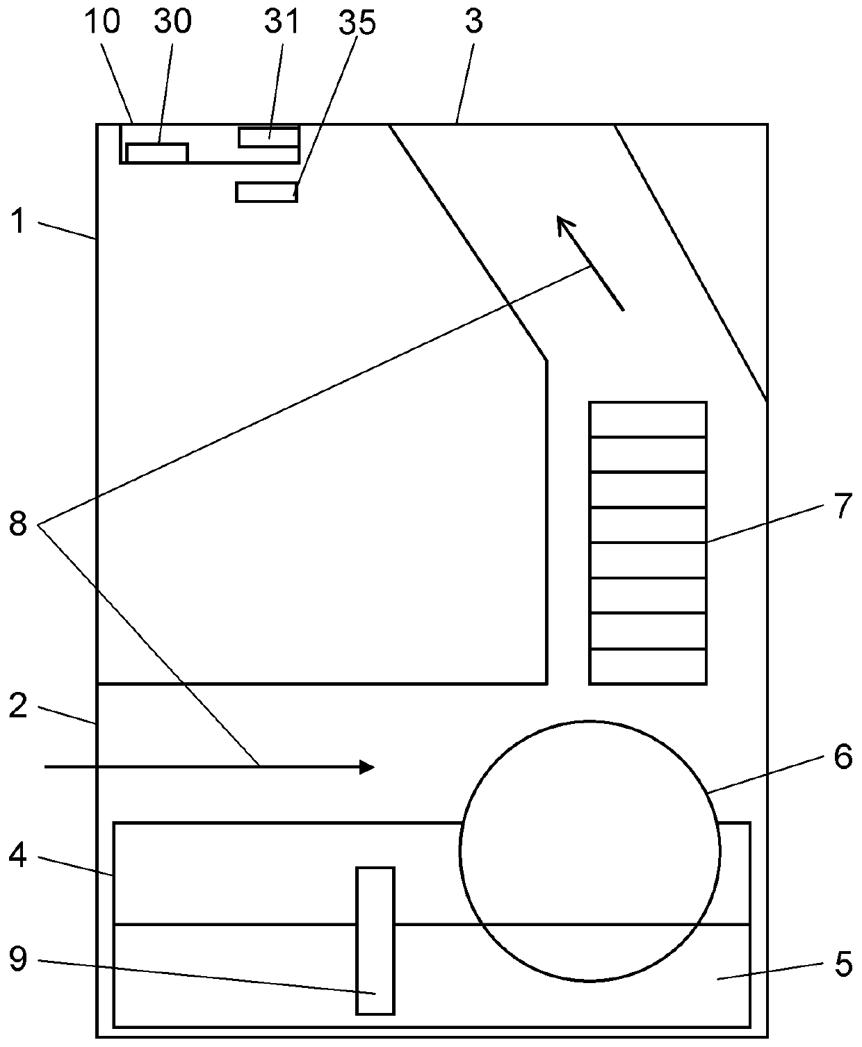
[0063] For the basic structure of the air cleaning device in this embodiment, by figure 1 A schematic cross-sectional representation of the . The housing 1 of the air cleaning device includes: a suction port 2, an air outlet 3, a fan 7, a filter 6, a liquid tank 4, an electrode unit 9, a sterilization air path 8, a display-operating part 10, a notification part 31 and a drainage detection unit 35 .

[0064] The suction port 2 is an opening through which air flows into the casing 1 . The suction port 2 is provided on the side of the casing 1 .

[0065] The outlet 3 is an opening for discharging the air inside the casing 1 . The outlet 3 is provided on the upper surface of the casing 1 .

[0066] The sterilization air passage 8 communicates with the suction port 2 , the filter 6 and the air outlet 3 . That is, it is an air path for sterilizing indoor air.

[0067] The fan 7 is connected with the motor, and the rotation of the motor generates air flow. This air flow is an ...


PUM


Abstract

An air purification device of the present invention includes an electrode unit that electrolyzes an aqueous solution stored in a liquid tank, and a control unit that controls energization of the electrode unit. The control unit detects the current flowing in the electrode unit. The control unit also performs specified energization on the electrode unit after a drainage detection unit detects thatan aqueous solution is discharged. The control unit allows a drainage informing unit to inform about the necessity of draining the aqueous solution in the liquid tank when the current flowing throughthe electrode unit exceeds a threshold value after the predetermined energization is detected.

Description

technical field [0001] The present disclosure relates to air purification devices. Background technique [0002] As a conventional air cleaning device, there is known a device that electrolyzes salt water to produce hypochlorous acid, and circulates indoor air through the device to remove bacteria and viruses. [0003] The device for electrolyzing brine is provided with an electrode voltage control unit for controlling the intensity of current flowing through the electrodes by PWM (Pulse Width Modulation) control, and an electrode switching unit for switching the polarity of the electrodes. Then, control is performed to repeatedly flow a large current and a small current between the electrodes for a fixed period of time with a current stop period, and control to reverse the direction of the current between the electrodes every time the stop period after the flow of a small current is performed. [0004] Here, in electrode control, if direct current is applied in a certain d...

Claims


Application Information

Patent Timeline
Patent Type & Authority Applications(China)
IPC IPC(8): F24F3/16F24F11/88F24F11/64F24F11/38
CPCF24F11/88F24F11/64F24F11/38F24F8/15F24F8/117F24F8/192F24F8/24F24F8/10Y02A50/20
Inventor 坂元悠小原弘士北浦理
Owner PANASONIC INTELLECTUAL PROPERTY MANAGEMENT CO LTD
Why Eureka
Try Eureka